WORK
IN PROGRESS
2019 update
It was my
intention when starting this page to provide a chronological photo essay
of the construction of the layout. Unfortunately I was lax on keeping
this page updated and over a decade lapsed since the last update. Part
of this was due to the somewhat sporadic nature of the construction with
great strides being made some years and very little in other years due
to life getting in the way. In the early days photos were taken with a
film camera then scanned into digital format for use here. This became
easier with the acquisition of a digital camera but it also meant that
the digital camera output often got stored of a number of different
computers and backed up on a considerable number of solid state storage
devices and when it came time to do a ten year update it became quite a
nightmare to find and organize things into the order in which they
happened. In some cases either I've lost track of some of the
progress photos or just never took any. What follows after the
photo from the fall of 2001 is the best I can construct from what I have
found so far. If more archive data is is found I will fit it in with the
rest.
In the
beginning...
The first spike
was driven early summer 1997. The RC&G uses code 332 aluminum rail
which is hand spiked to 1/2" x 1" wooden ties. The ties are double
height which allows for more ballast to cover the base to which they are
attached and protect it from UV rays which tend to do the most damage to
treated lumber. Tie size and rail code were chosen giving preference to
durability over scale appearance. The ties are attached to 3/4" treated
plywood which has been cut to a width to match the ties. Ties are
attached using annular ring nails. Ties are milled by the RC&G shops
from treated lumber and then stained to give the appearance of creosote.
Each section is approximately 8' long and built on a bench. The sections
when complete are floated on 2 - 4" or more of crushed limestone
depending on the amount of fill required and ballasted with 1/4" and
finer crushed limestone.
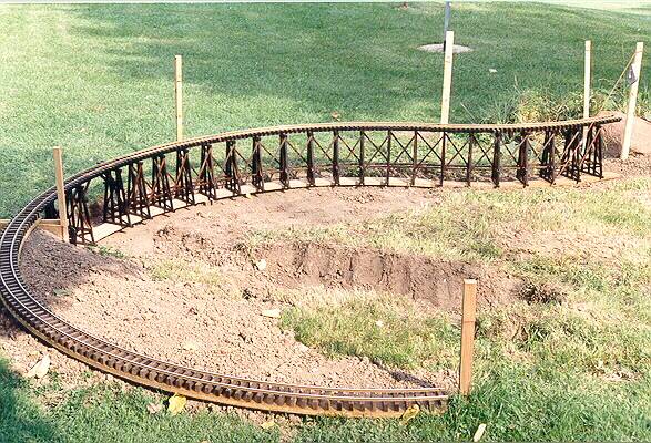
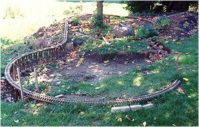
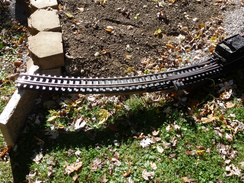
1997
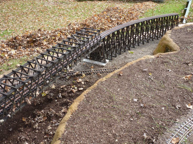
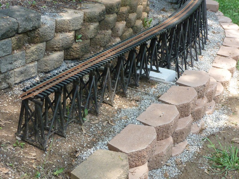
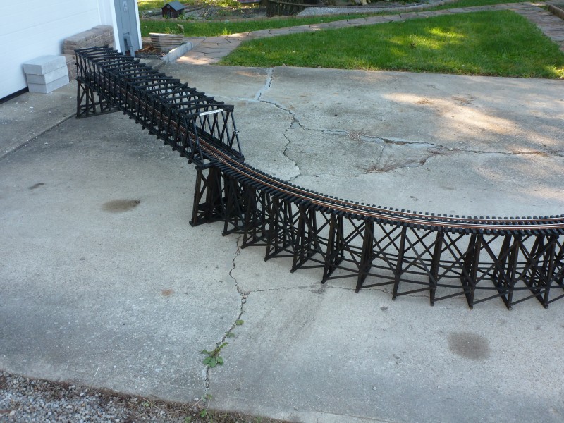
This is where it
all started. The trestle was the first thing built. Pressure treated
plywood was cut in the 'S' shape the trestle was to take and it was
marked for the locations of the bents. The bents were also made from
well dried PT lumber and assembled in a jig using glue and finishing
nails. Once completed they were attached to the plywood base and the
stringers and cross bracing attached. The ties were then attached and
the rails spiked down. The lead in track was built and when complete
construction began. The stake in the front set at the highest
point on the line is used as a reference to set grades. Track is level
till it reaches the trestle and then begins a 3% decent. Stakes toward
the rear mark reference points at 1" increments of decent.
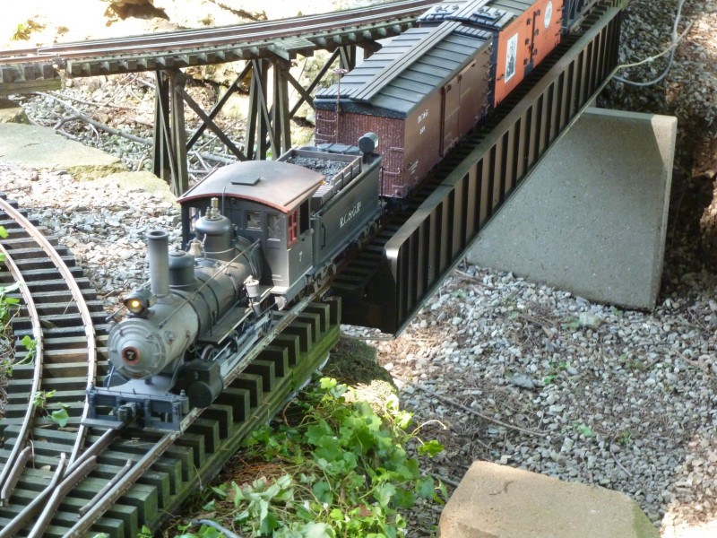
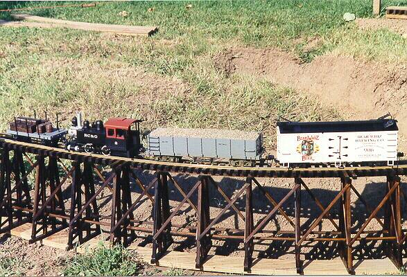
The
first train to run on the RC&G
The next photo
shows the extent of trackage as of October of 1998, mostly weed grown.
Unfortunately the Summer of 98 was filled with higher priority projects
and the railroad saw little in the way of progress.
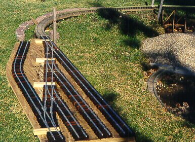
During
January of 1999 the north end of the main yard at Summit was built, this
photo shows it set into the position it will occupy when favorable
weather returns. The switch ties have not been stained pending
installation of Del-aire switch machines.
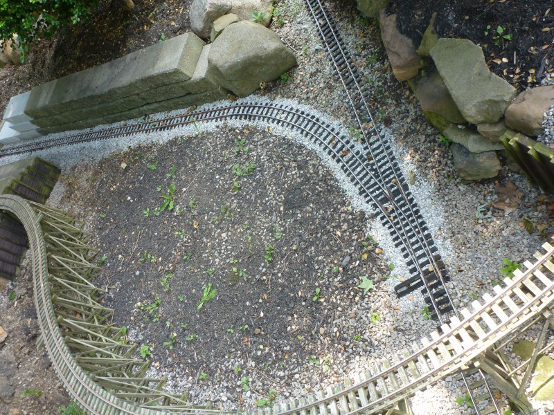
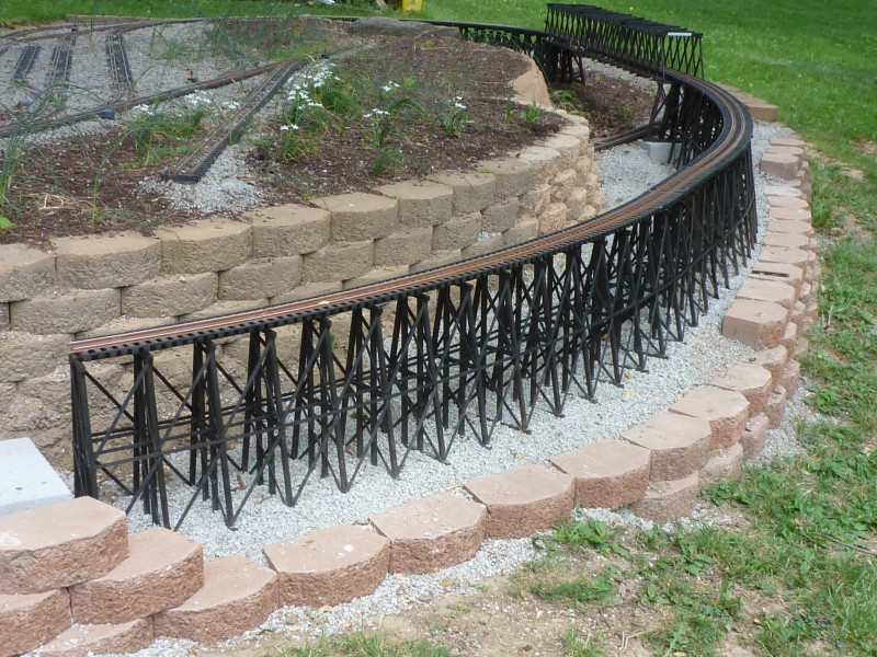
The summer of 99
proved to be much more productive than that of 98. A change was made in
the overall plan that converted this end of the line into a return loop.
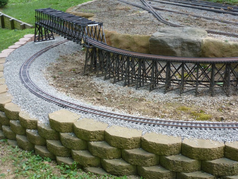
This required a lot of fill and a retaining wall to be built. The work
on the yard at Summit was completed and installed as well as the
additional track work required for the loop. The photos that follow show
how the line looked at the end of season 1999.
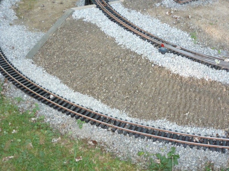
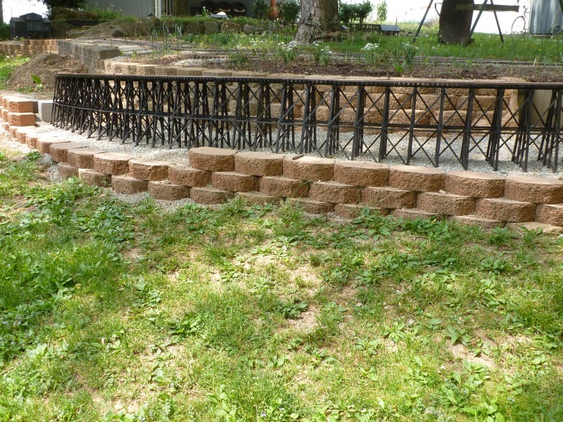
This shot shows the southern end
of the yard at Summit. The track to the far left is nearly a foot lower
than the yard and is descending down Raccoon Gully. The branch going off
towards the rear is a spur to service a retail coal distributor, The
Ohio Valley Coal Company and the RC&G freight office.
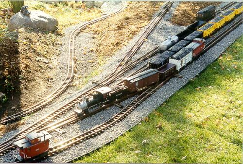
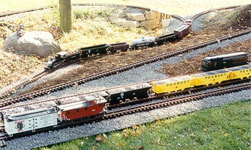
This is another
shot of the yard with a train descending the grade down Raccoon Gully.
Where the doodlebug is parked will be the location of the station at
Summit.
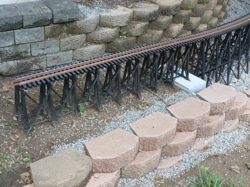
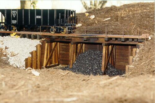
This shot shows
the coal dump that will service the Ohio Valley Coal Company.
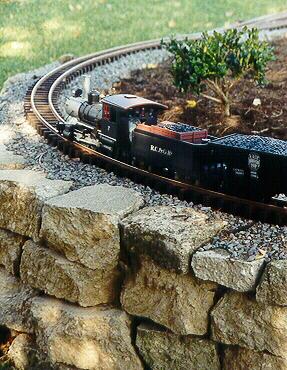
This shot shows
RC&G #7 working hard upgrade to the yard at Summit. Stone work is
part of the retaining wall built to retain the fill at this point on the
line.
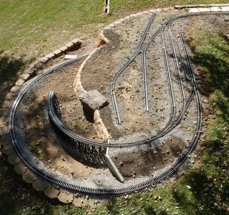
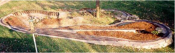
This is an
aerial view of the RC&G at the end of Summer 1999, for reference the
total length from side to side in this shot is forty feet.
From the Fall of
1999 till the Summer of 2001 most of my available layout building time
was consumed by family issues and no further work was done until the
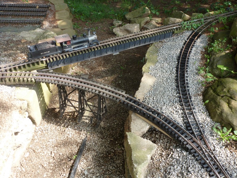
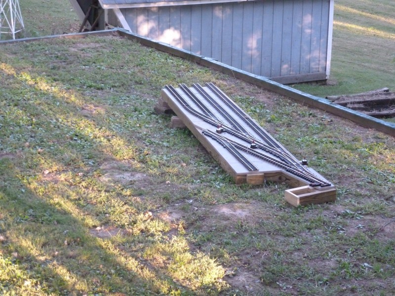
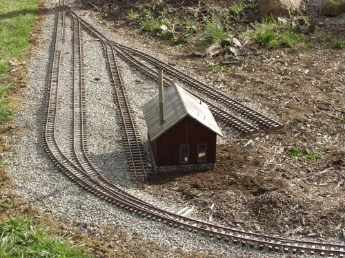
Fall of 2001 when the first part of phase two was added. This section
starts where the line passes under the "S" curve trestle and consists of
a curved turnout leading into a passing siding and the track work which
will become the RC&G's engine servicing facilities. Included in this
is a 3 way stub switch.
The building is the power plant
for the engine facility. The 2 stall engine house will be located at the
end of the two tracks next to the power plant. The power plant
building sits over a junction box where air and electrical services from
the garage are located.
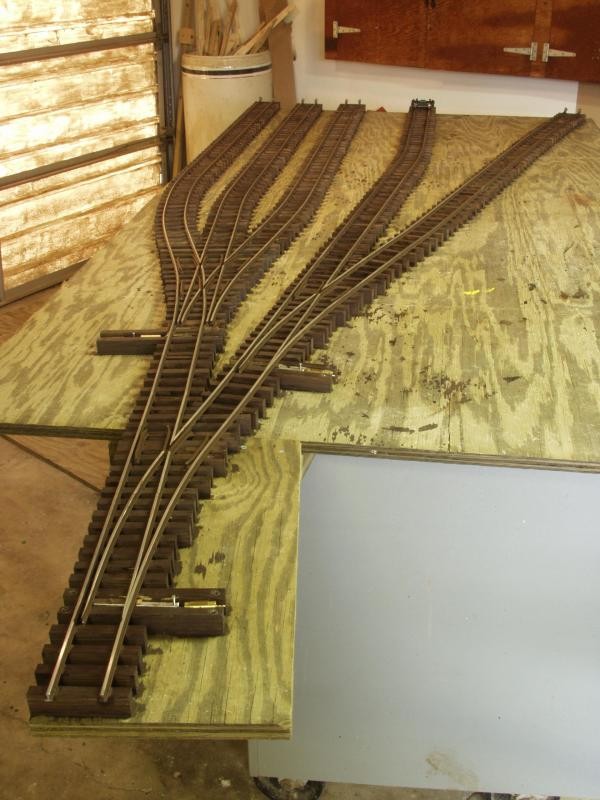
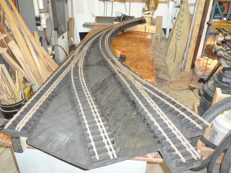
Above the end of
the track in the above shot the track curves to the left and enters the
town of Lynville where the Rockhill mine, the source of most of the
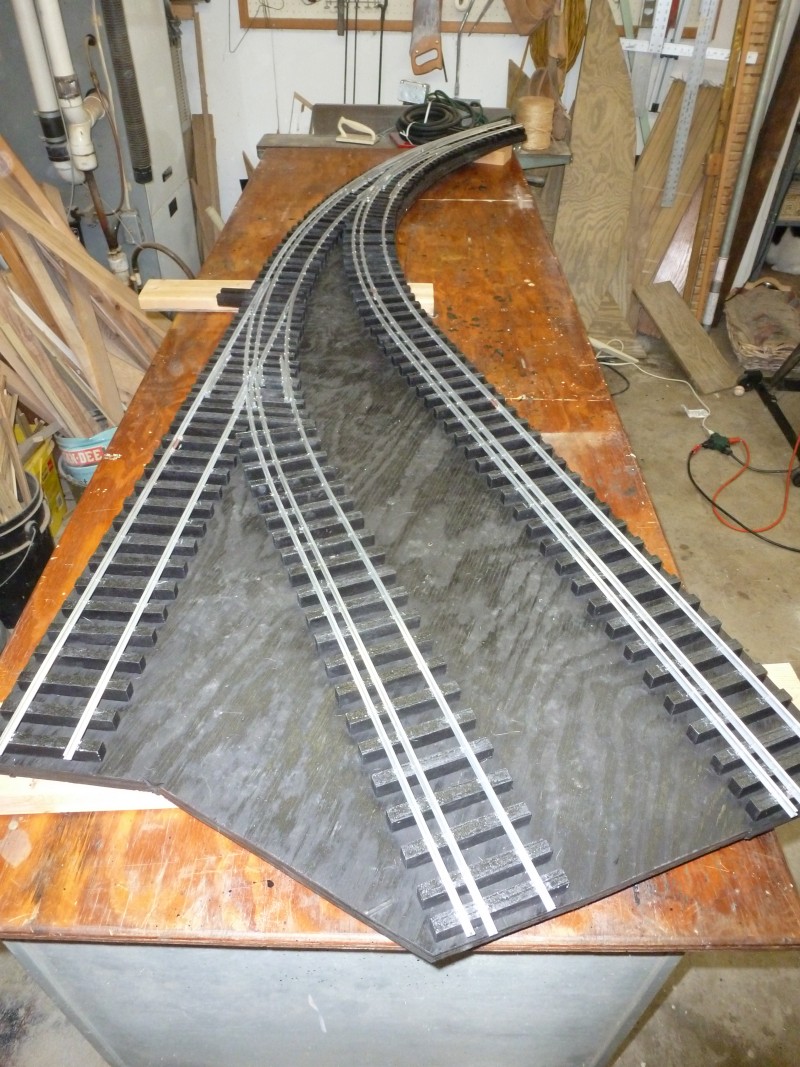
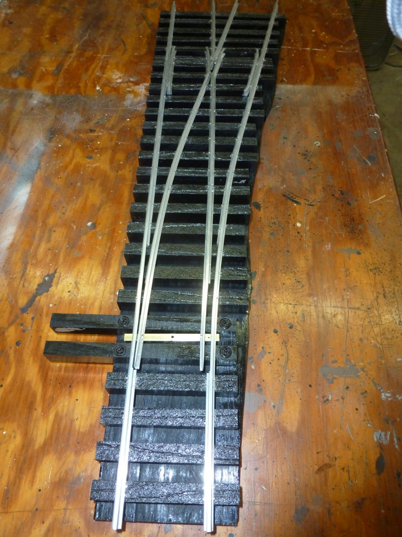
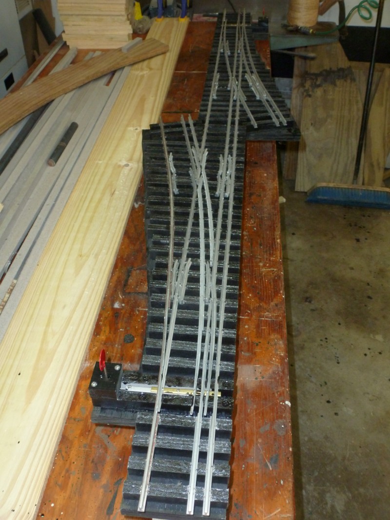
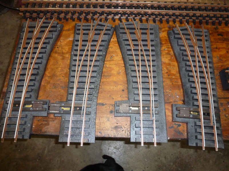
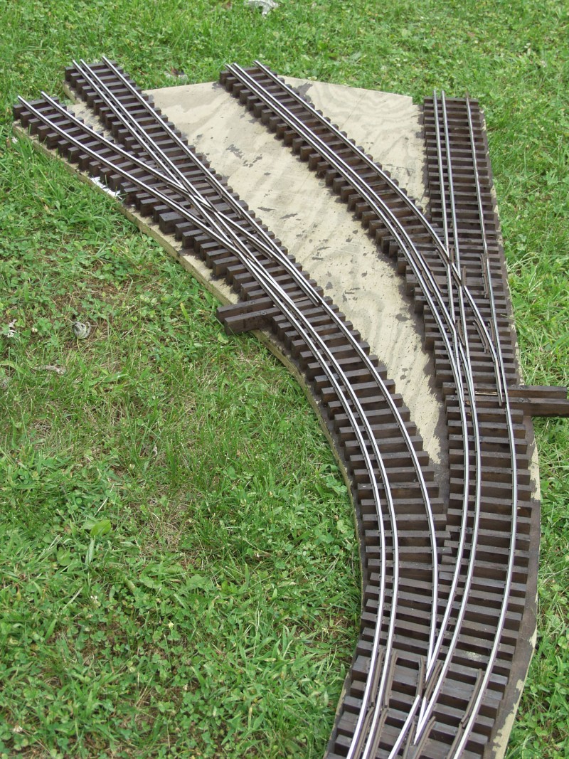
RC&G's income is located. Before I could begin work on this section
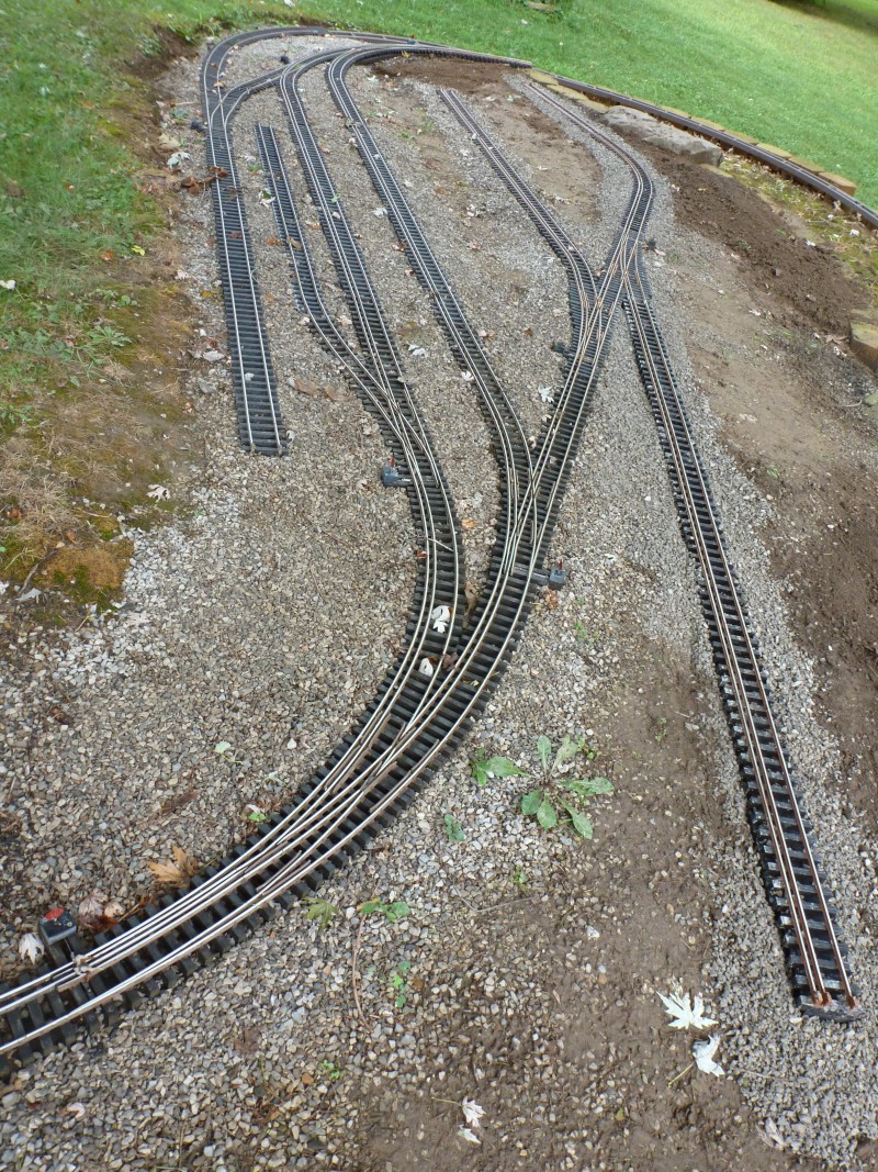
I needed to fabricate the track work for the mine coal cleaning plant.
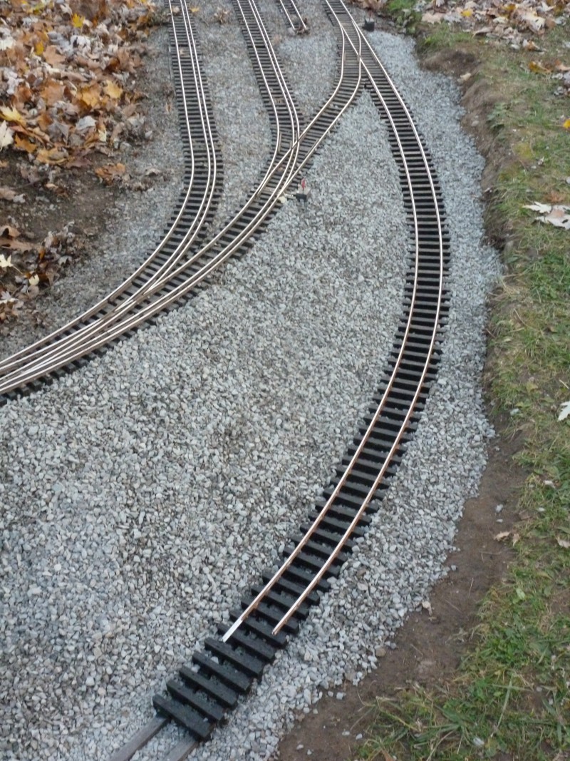
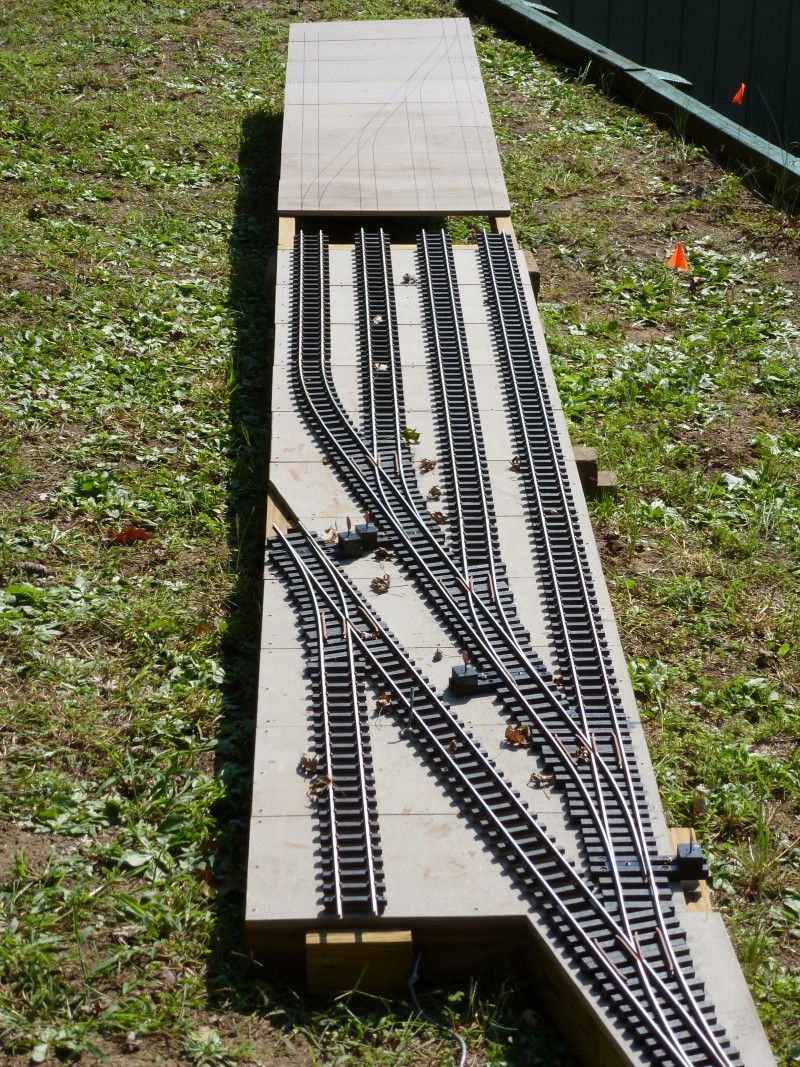
There was another couple of years with little or no new progress but
during the winter 2003 -2004 I finally fabricated the mine track work.
The three tracks to the left service the loading tracks for the coal
cleaning plant, the other two serve to store empties or loads as
required and the fourth track from the left also provides loading for
the waste from the cleaning process.
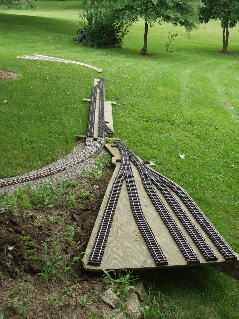
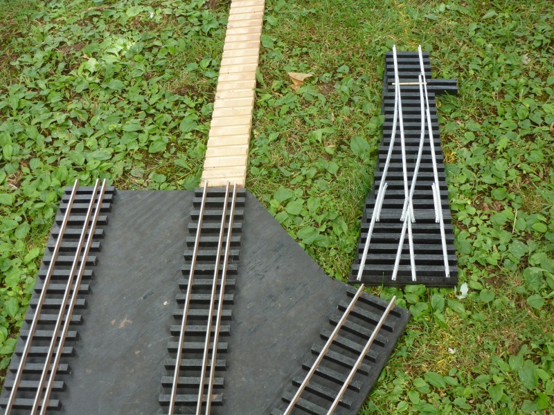
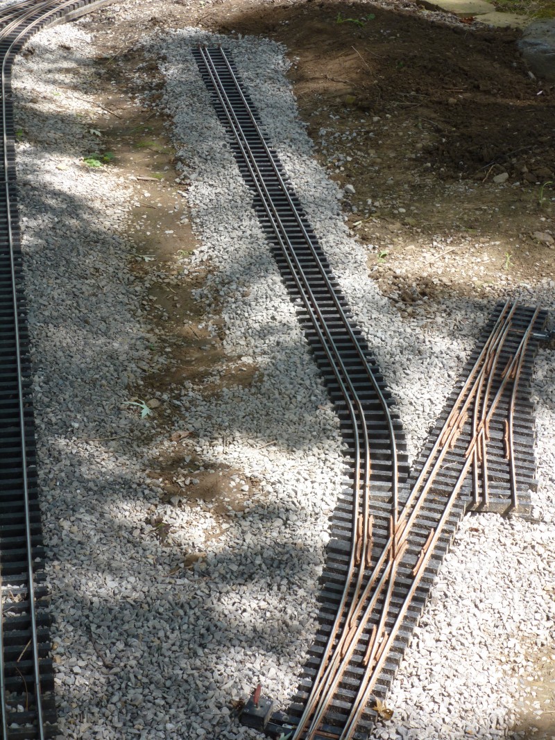
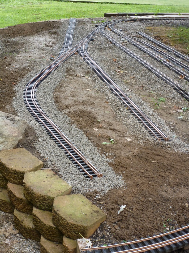
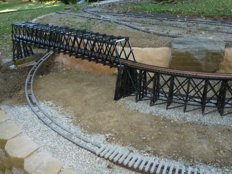
This
piece and the next portion of the line was set in place in 2004. At the
far end starts the beginning of the dual gauge interchange.
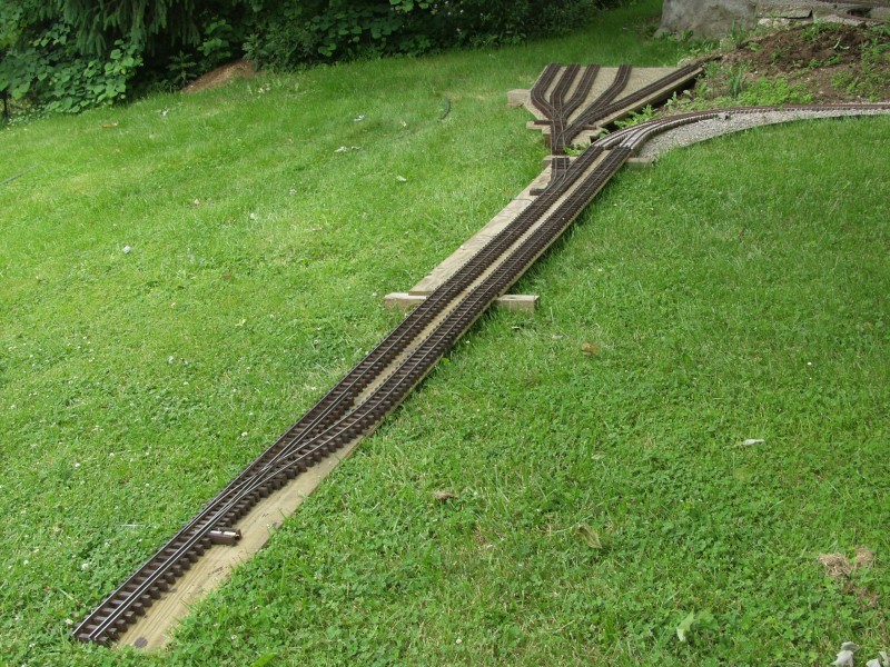
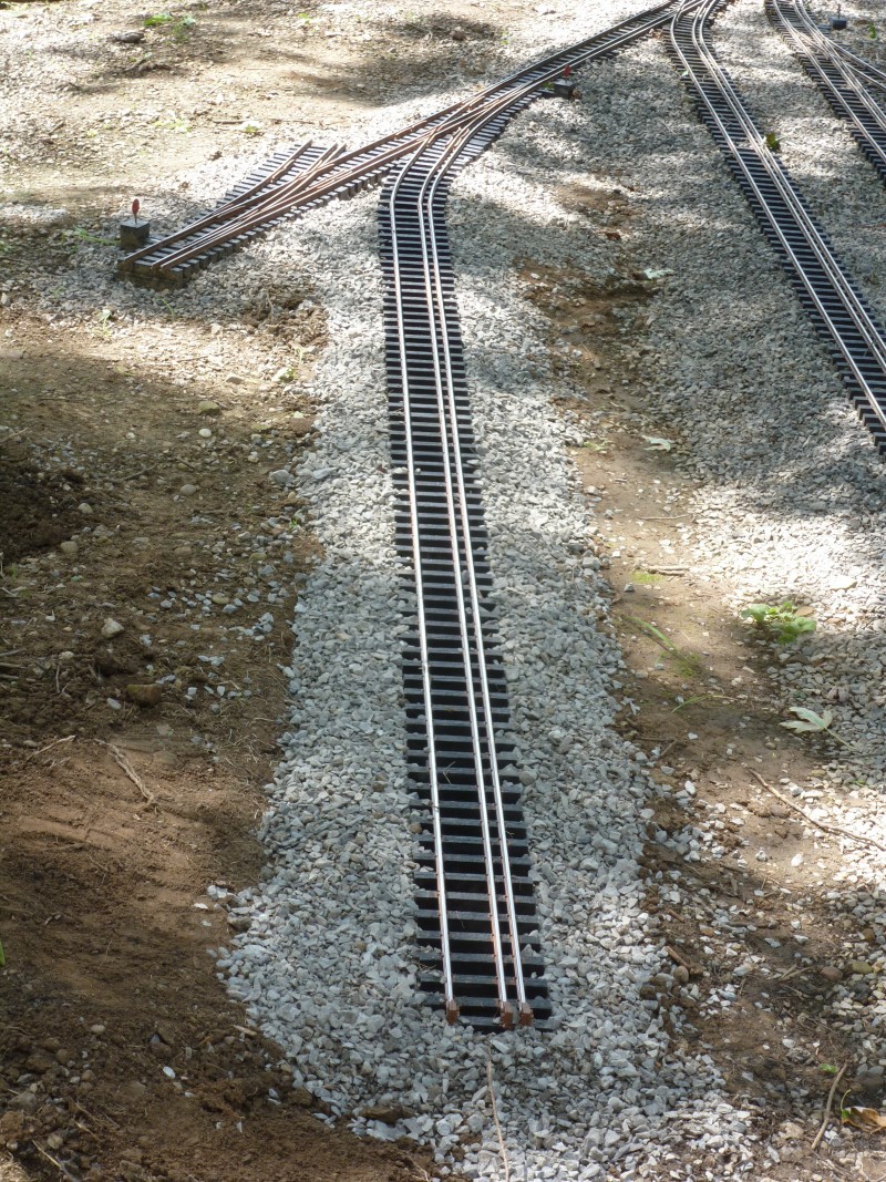
A
view from the other end. At this point everything was just set in place
to get an idea of what was needed in the way of fill and other
landscaping features. Much needed to be done especially in the way of
retaining walls as this track work at this point set on the edge of a
slope.
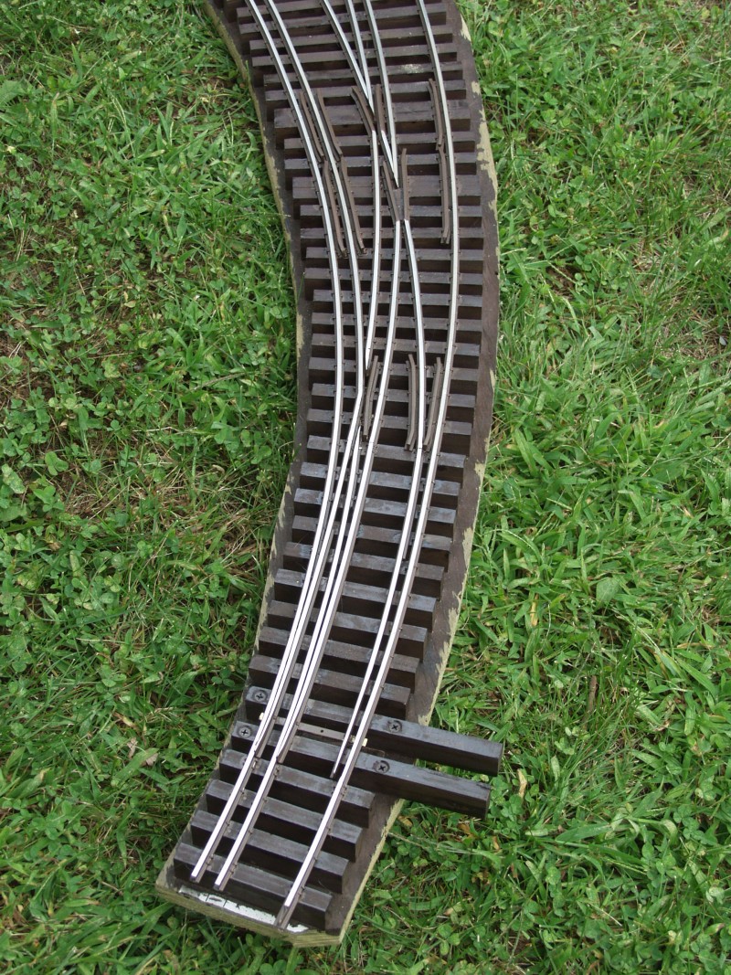
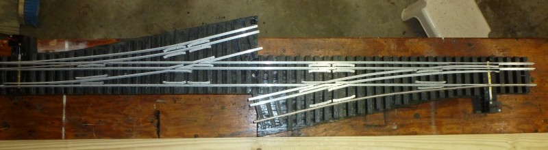
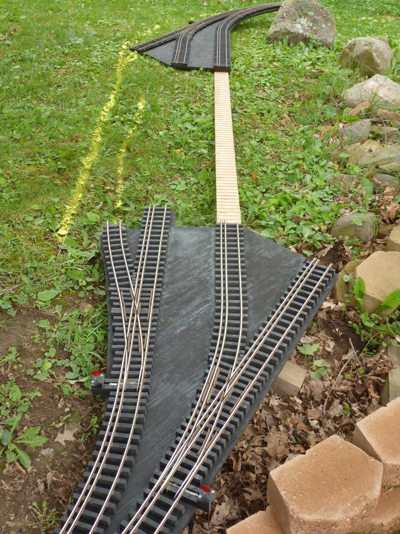
Also
completed in 2004 were the beginnings of the dual gauge interchange with
first two of the most challenging switches built to this date a curved
and straight dual gauge.
The
narrow gauge branch to the left will be an interchange track for
transferring freight between the gauges.
In
2004 a major retaining wall that would level the ground in the area I
intended to enclose the balance of the layout was started. A planned
home improvement project that would expand the house's foot print would
create a fair amount of fill from excavations for the foundations and
crawl space and I needed some place for that to go. It was only
partially completed, just enough to retain the fill I had and much of
the balance of 2004 and much of 2005 was consumed with the house
additions. Some work was done both on layout and other layout related
projects. I either didn't document much of what was accomplished or if I
did I have lost the photographic evidence of it. If any of it turns up I
will add it here. From 2005 through early 2009 the layout stagnated
except for occasional maintenance. My Wife's health was in decline and
between work, housework, yard work, grocery shopping and taking my Wife
to doctors and caring for her, I just didn't have time for much hobby
work of any kind. After she passed in early 2009 and for the balance of
the year my life was pretty much in turmoil and I had little to no
interest in doing anything hobby related. Finally in 2010 I began to
snap out of it and started getting back into things.
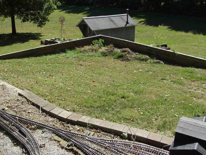
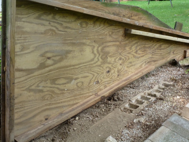
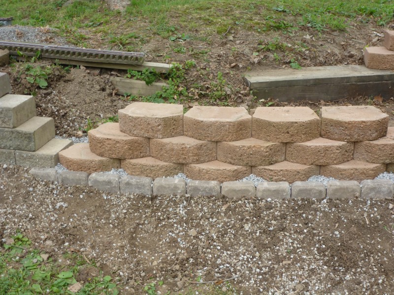
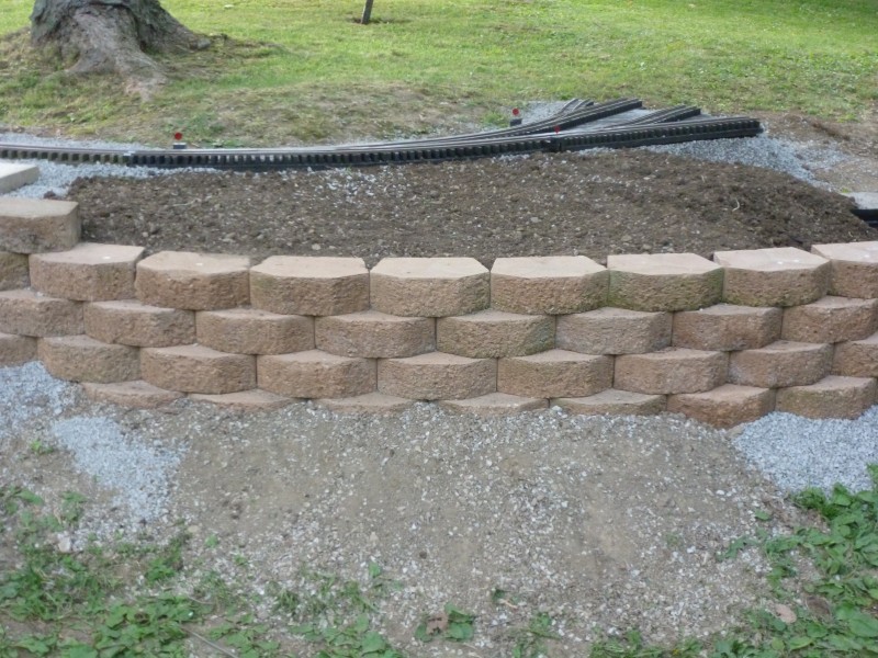
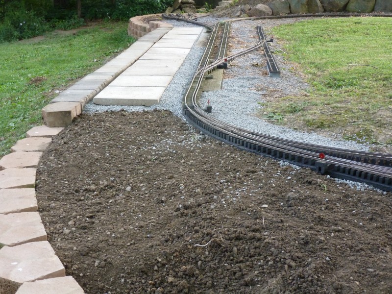
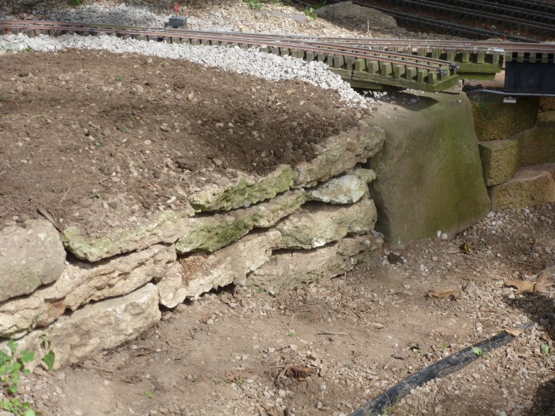
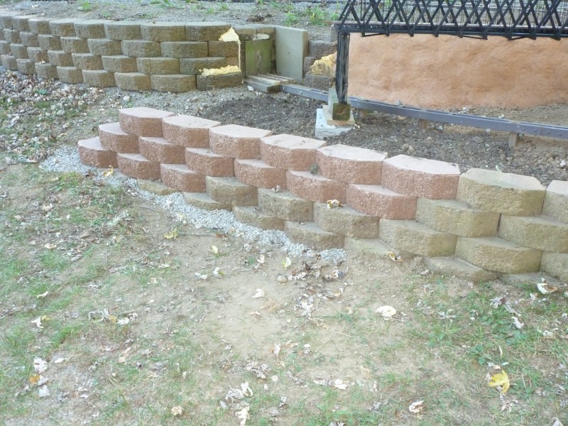
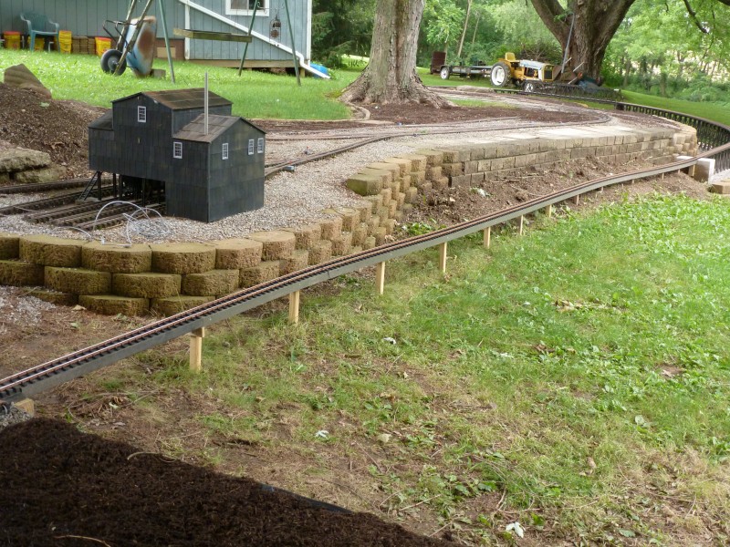
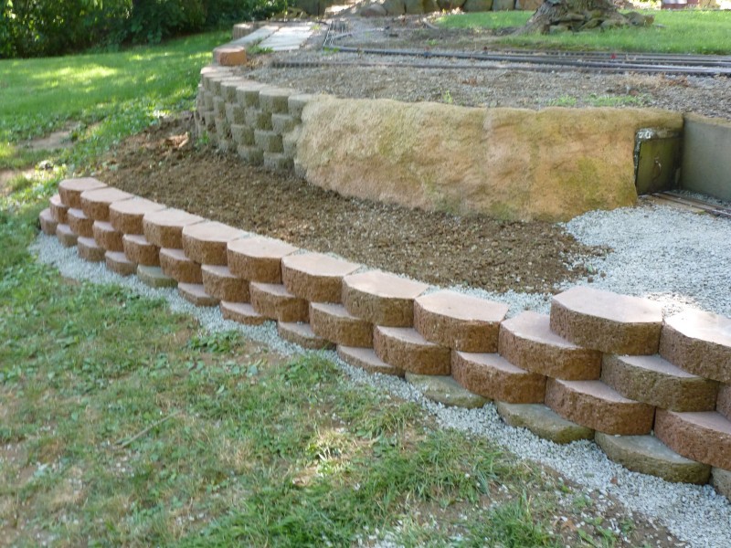
First thing that needed done was completion of the main retaining wall,
the photo below shows the wall after it was completed but before the
balance of the fill was added. In the foreground can be seen the stacked
retaining wall that was built to level and retain the area around the
mine and the area where Lynville will be located. Note that the height
of the main retaining wall at the corner near the shed is nearly six
feet high.
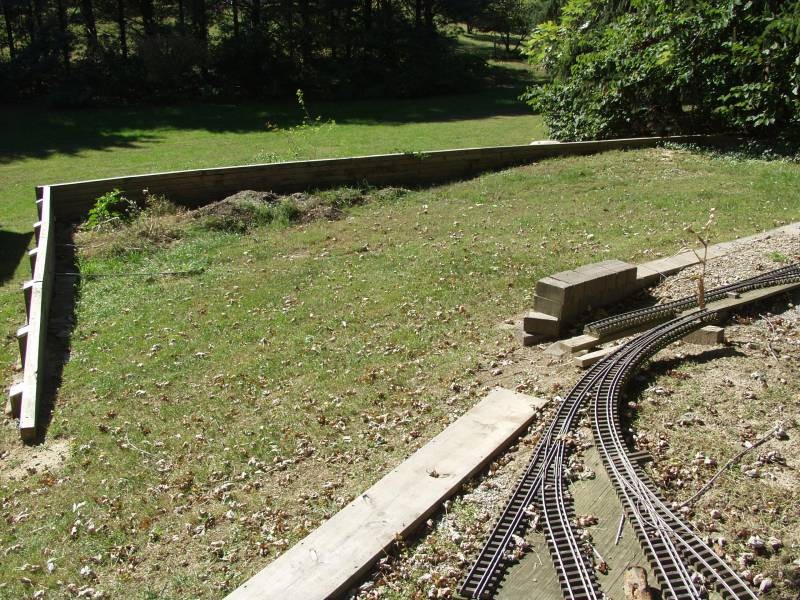
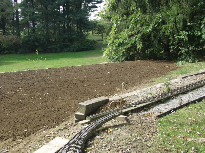
Here
is another view.
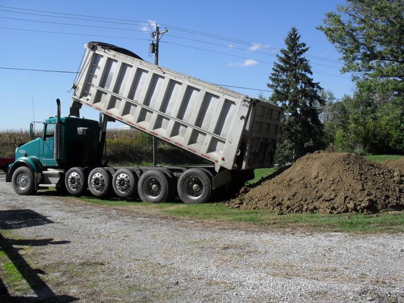
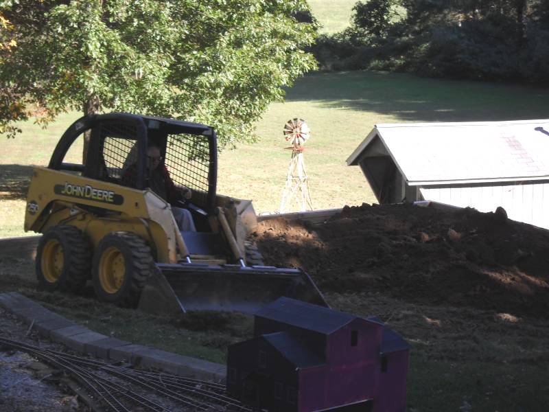
In
the fall of 2010 I had fill trucked in, the first of three truck loads
is shown below.
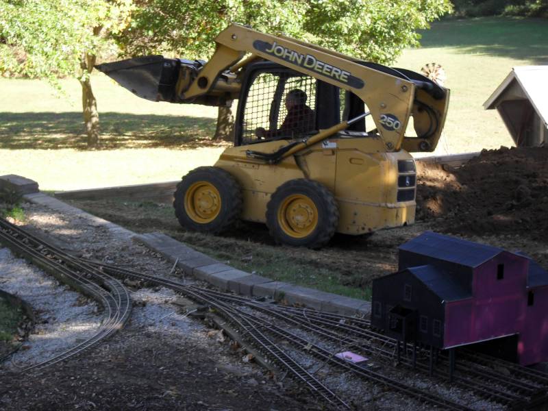
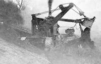
And
I rented one of these to do the heavy lifting.
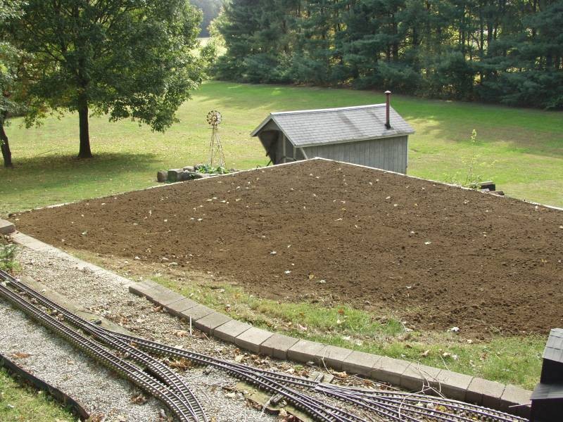
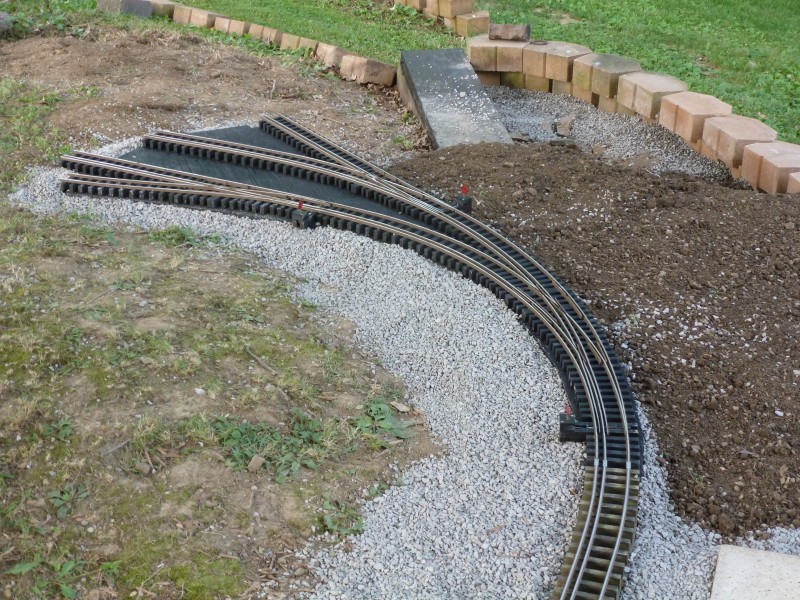
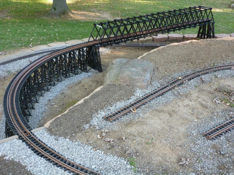
The
end result is shown next.
It
can be seen in the above photo the end of the track work at
Lynville and the beginning of the dual gauge interchange as been left at
the mercy of the elements and has set mostly untouched for years and not
properly set allowing it to become warped and twisted and this would
need to be corrected before additional work could be continued. From
late 2010 to 2014 I have very little in photos and it seems that not
much was accomplished. This could have been the result of a number of
things including getting my social life back on track. I retired at the
end of 2013 but early in 2014 my former employer hired me back as a
consultant and the first four months of the year saw me putting in a lot
of hours doing consulting work. When that was finished though I started
attacking layout projects with a passion and I have a bunch of photos
from that year so we'll pick up things from there.
2014
2014
ended up being as much a year of rebuilding as it was building anew.
Even the newest portions of the layout were now 10 years old and during
that time were only given minimal love and some areas were in need of
freshening up and restoration. The idea of using taller ties to keep the
substructure covered with ballast and out of the deteriorating UV rays
of the sun had failed in some areas due to my lack of diligence in
keeping said areas properly ballasted. Also some areas I felt could be
improved both from track design and landscaping. The first area to be
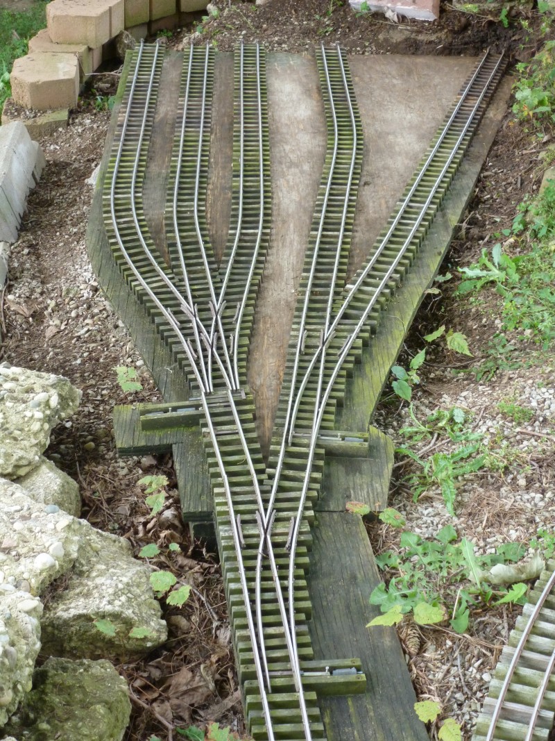
tackled was the track work and landscaping at the Rockhill mine. The
photo below shows what it looked like after it had been cleared of mud
and debris it had accumulated in the decade since it was installed. The
area had never been properly ballasted as I wanted to cover the area
with real crushed coal. For the most part everything was still
sound but there were some deteriorated ties and the upper surface of the
PT plywood had suffered from sun exposure. Notice that the switches were
still air powered. Something I had abandoned for the most part several
years earlier. Also the stacking block wall on the left was failing most
likely due to an insufficient base when originally installed.
The
first thing done was to disconnect the section from lead track and
inspect the underneath side. Fortunately the PT wood was all completely
sound there so only the top side would need work.
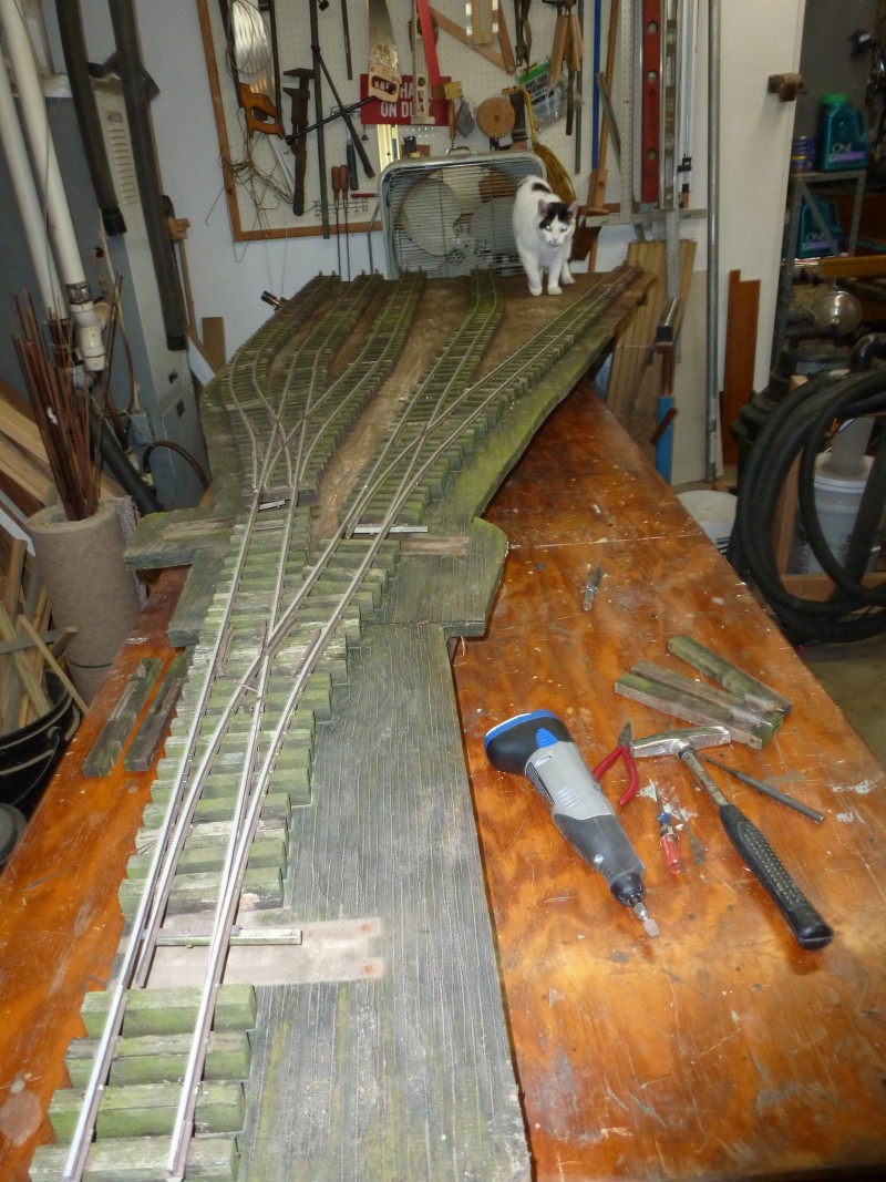
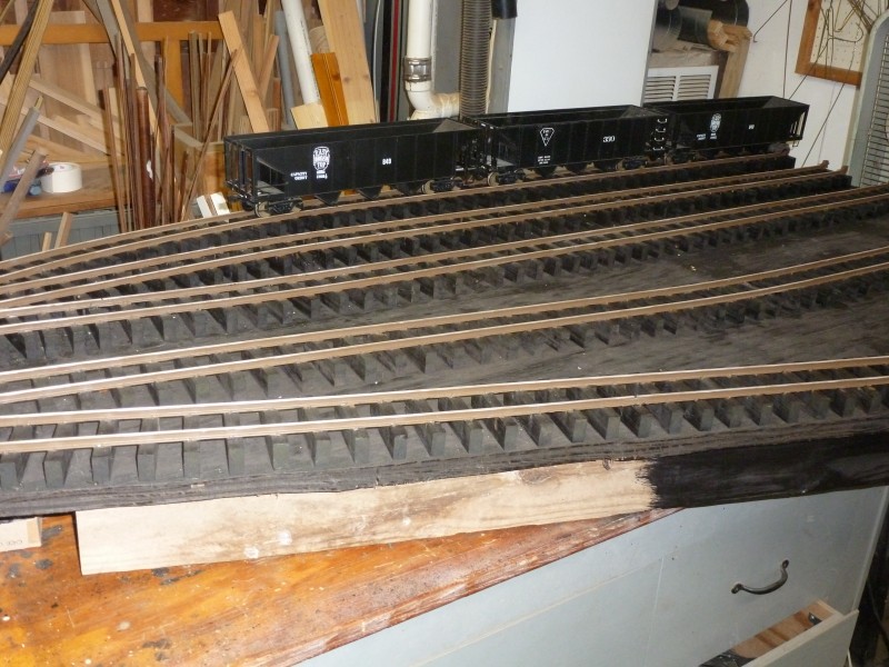
The
entire section was then moved to the track work bench in the shop where
the necessary work could be completed at a comfortable height. In the
next photo the point ties have been removed for replacement along with
air actuators. One of my inspectors is busy checking it out.
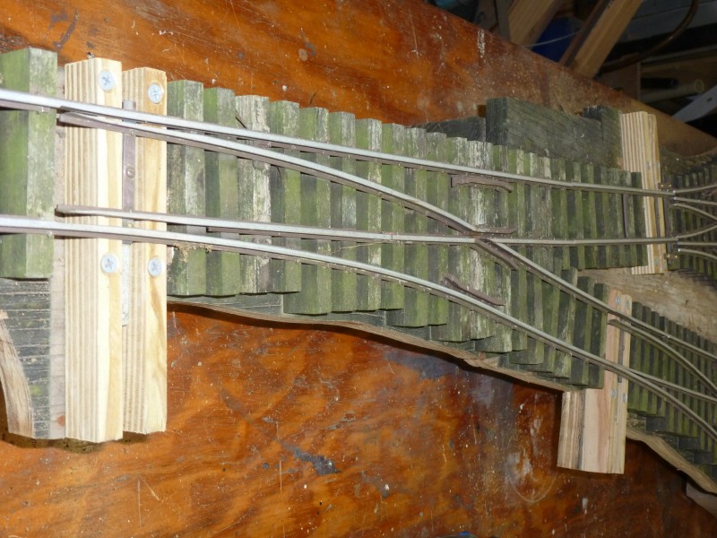
New
point ties have been installed. These are held in place by coated deck
screws. This will allow easier replacement if ever needed.
Any
unsound ties were replaced. The original ties had been nailed in the
area that was covered by the base of the rail, the new ones had to be
nailed outside the rail. The other ties may look rough but it's partly
due to being buried in mud and they still have a coating of it on them.
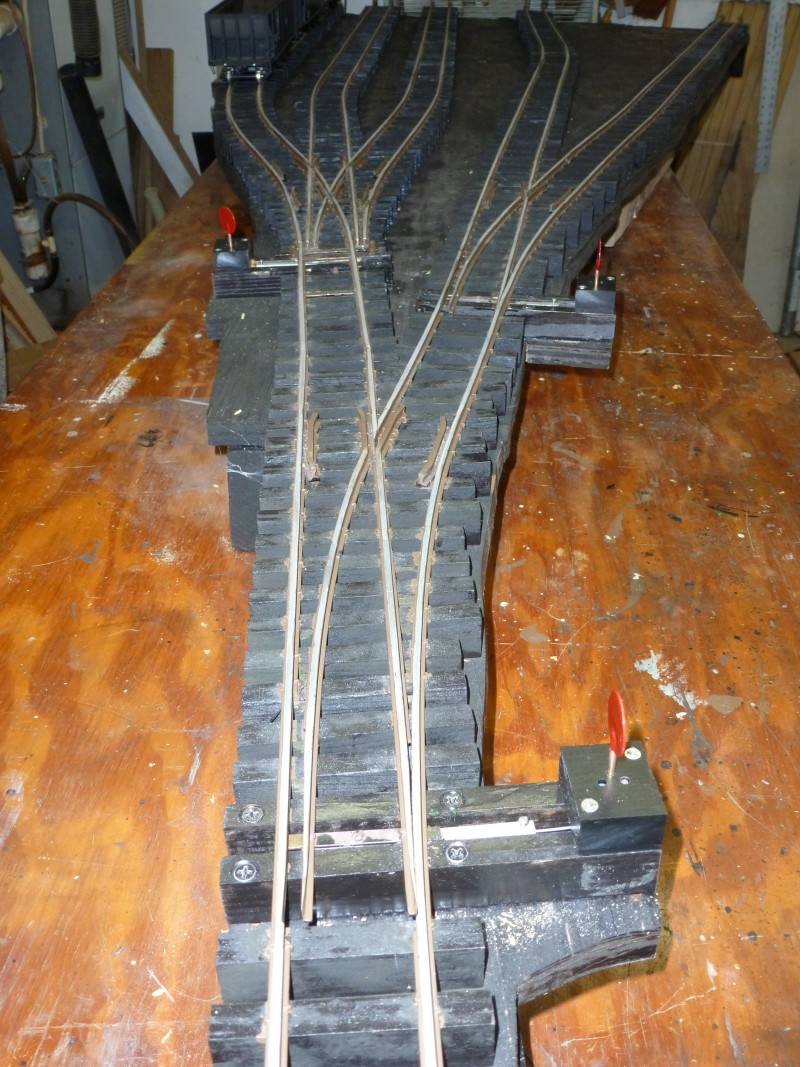
Once
the new ties were all in the ties and the exposed area was given a coat
of my homemade stain which is a 50/50 mix of oil based ebony stain and
boiled linseed oil. My own designed and built ground throw switch
machines were installed as well and the section is ready to be returned
to the layout.
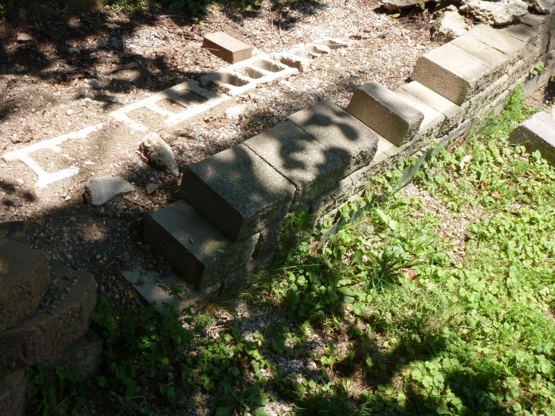
But
before that could happen the mine site it self needed some work. The
failing stacked wall needed fixed. An additional item on the agenda was
to lengthen the lead track from main as it was found to be a bit short
in actual operational use.
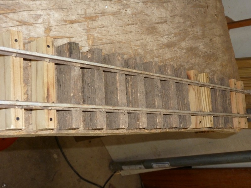
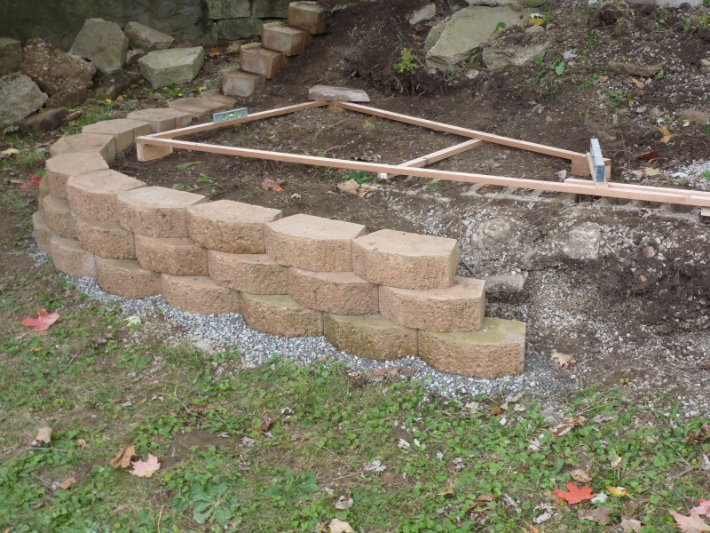
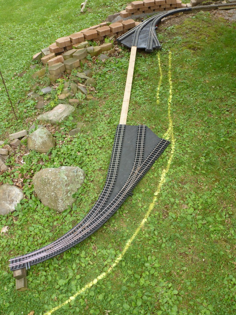
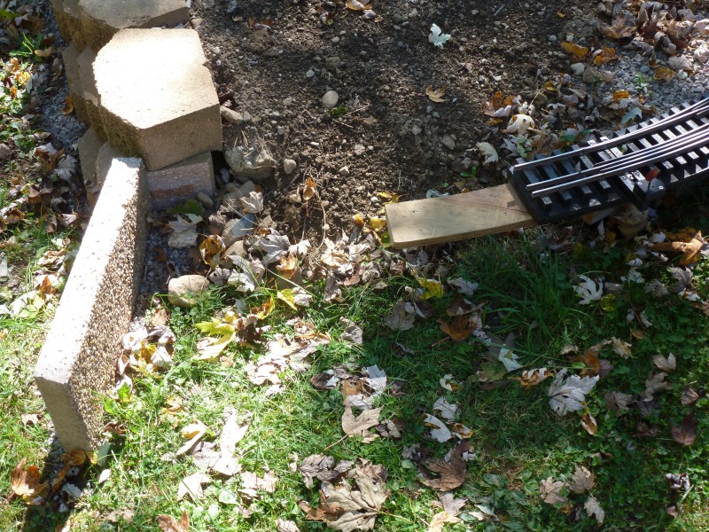
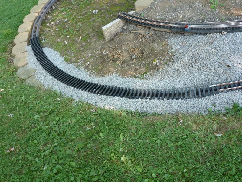
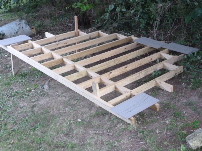
What
I needed was a way to see what all had to be done without hauling the
actual track section out, which is quite heavy and somewhat awkward to
move around. My solution was to make up a light weight frame that
mimicked the size and shape of the section but was light enough to be
easily moved and positioned until I was happy with everything. The photo
below shows the frame. It's setting roughly where I wanted it to achieve
a longer lead track. It was obvious that the stacked wall at the bottom
of the photo would also need to be redone so the whole process became
somewhat of a major operation.
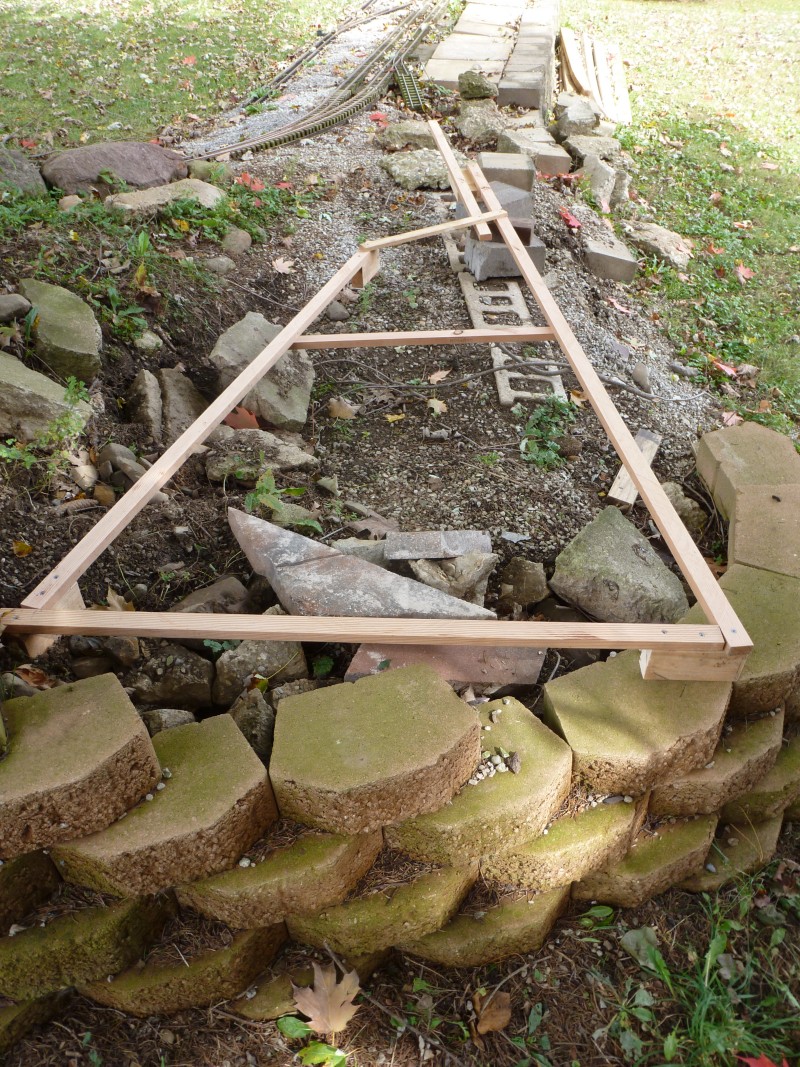
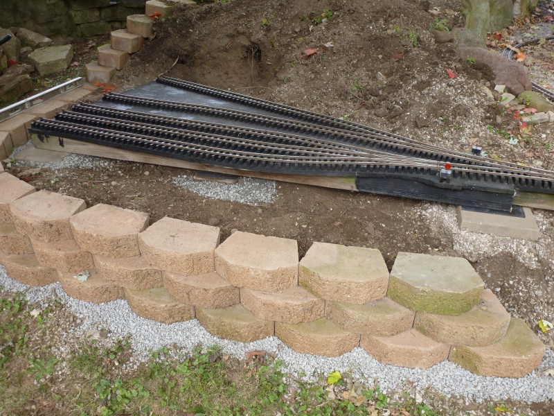
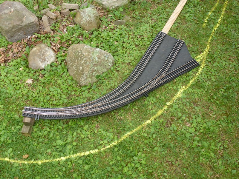
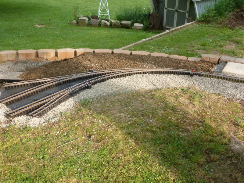
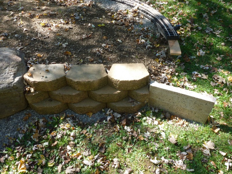
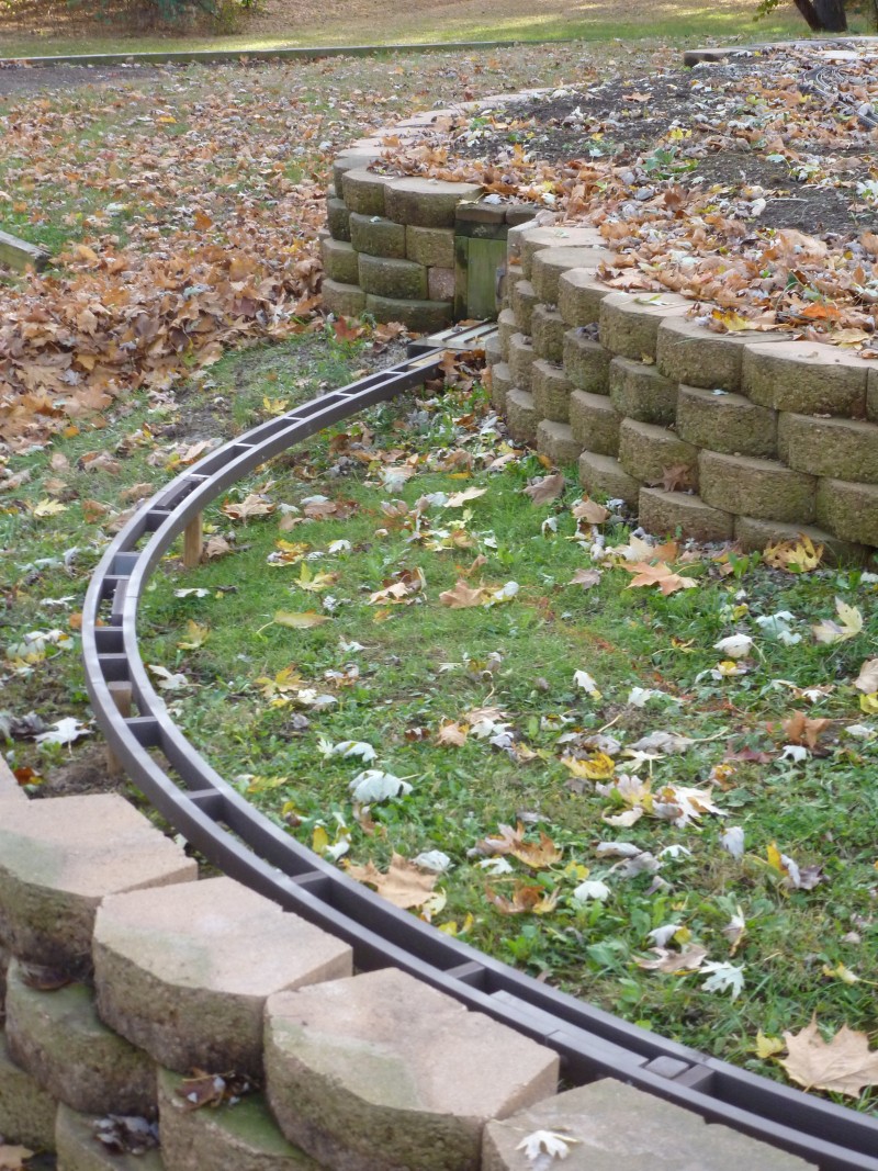
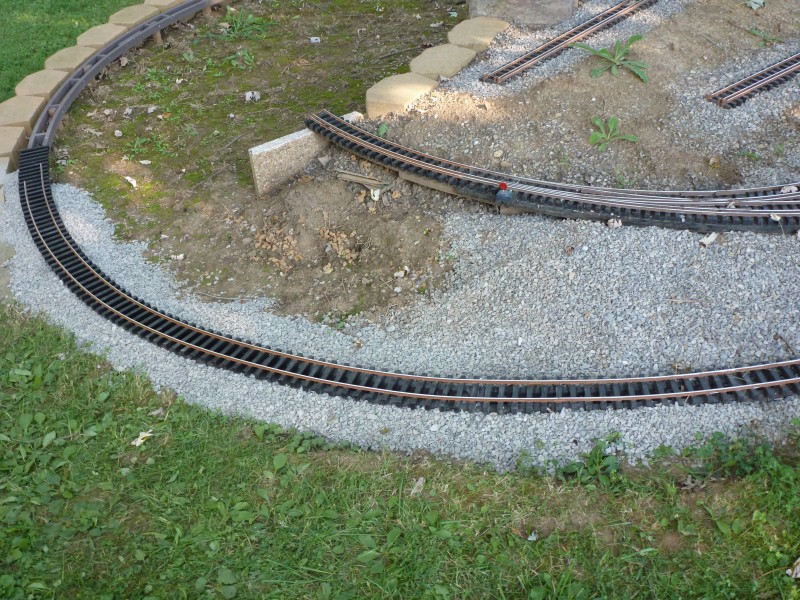
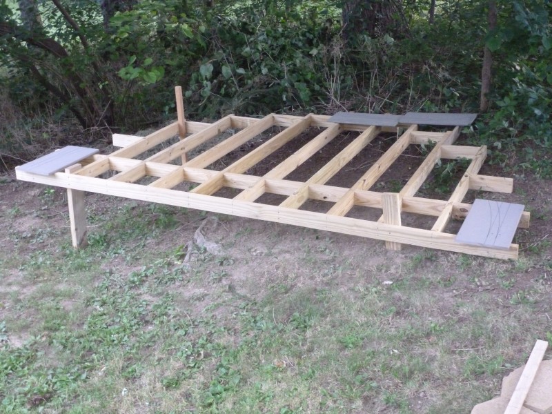
The
next photo shows the frame again after the curved stacked wall had been
rebuilt and moved outward more than the original section of
straight wall. The was to provide more room for the coal cleaning plant
and mine head frame. Some fill had been added and crushed limestone
would be used to fill in both under and around the mine track work.
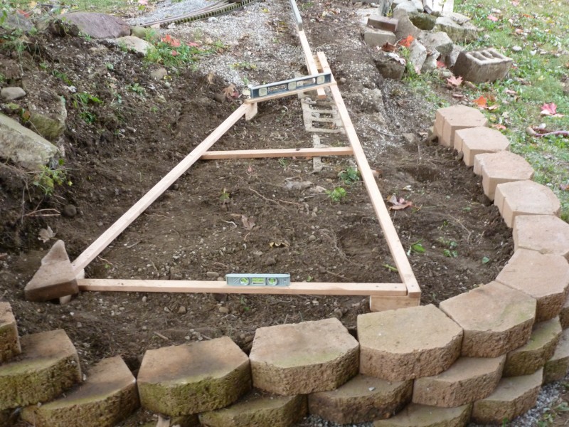
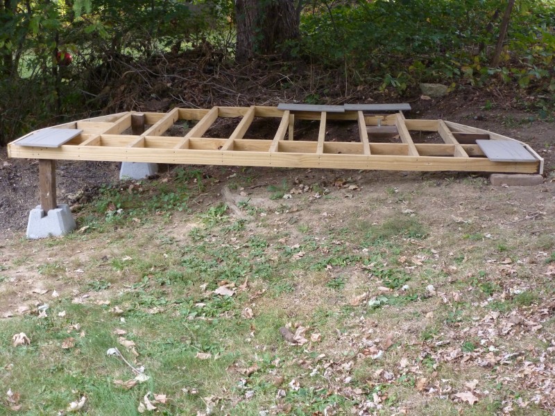
The
photo below from a different vantage point. Note that the stacked wall
got a sufficient base of crushed lime stone this time around.
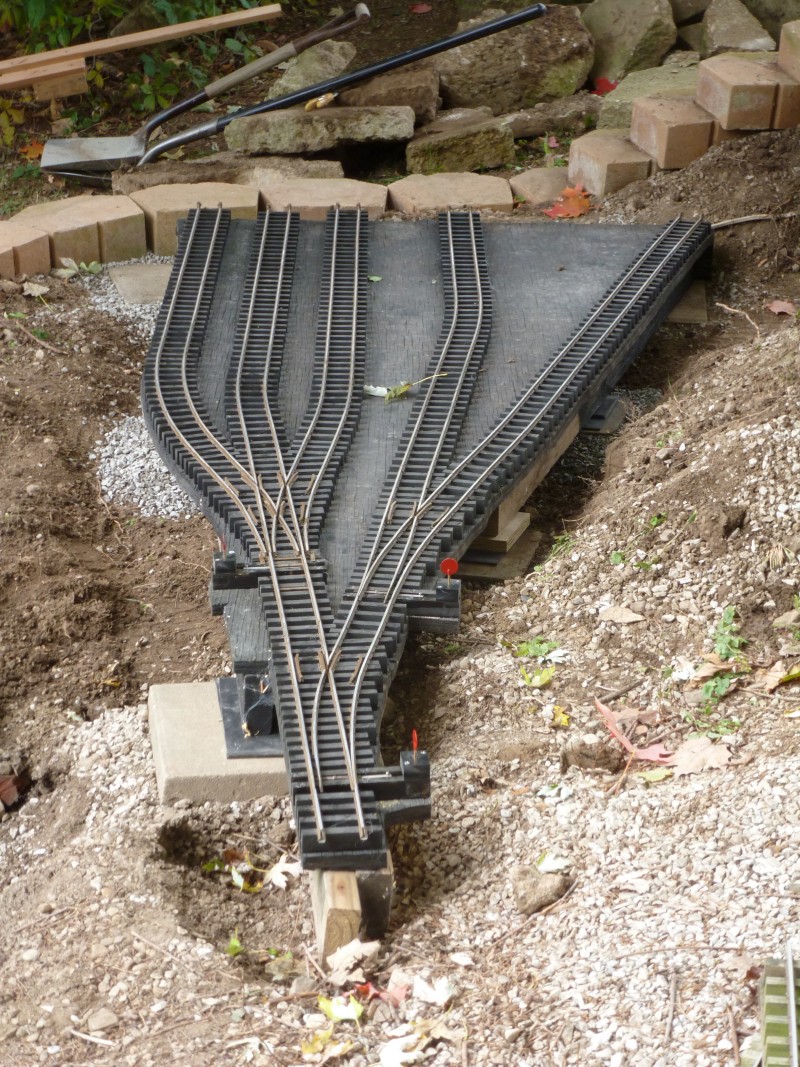
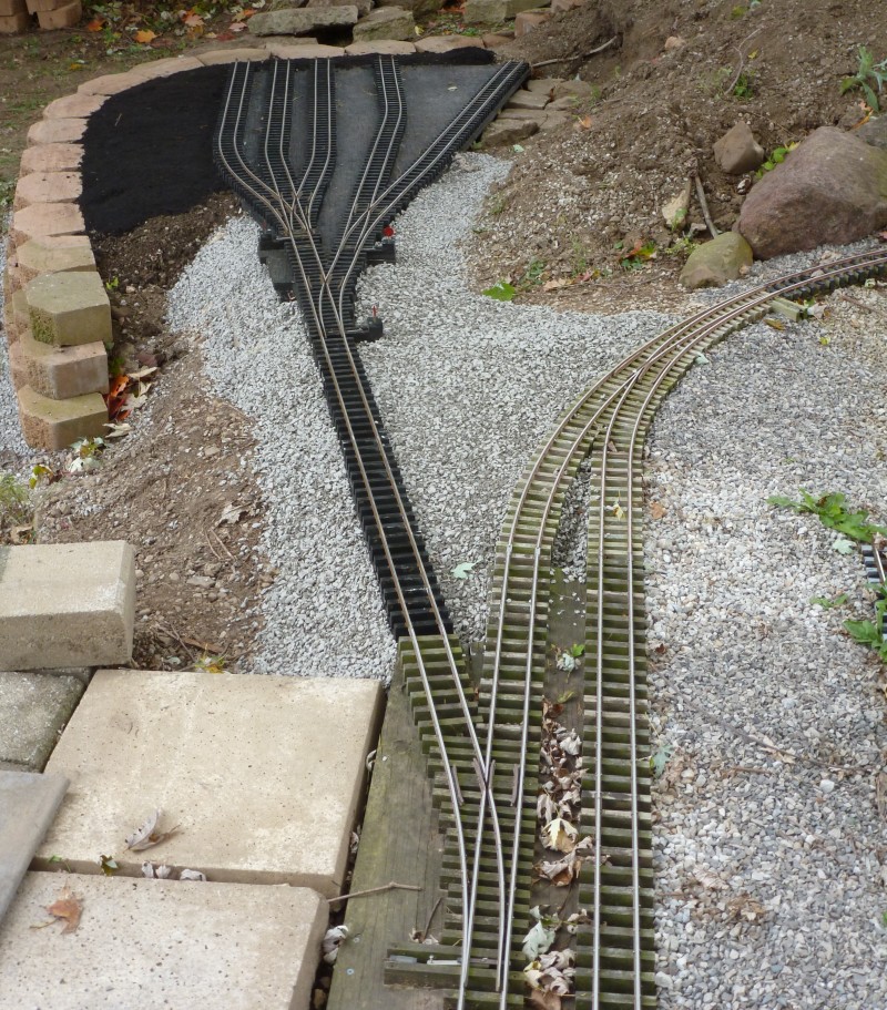
The
track work was then set into position and leveled.
A
view from another direction.
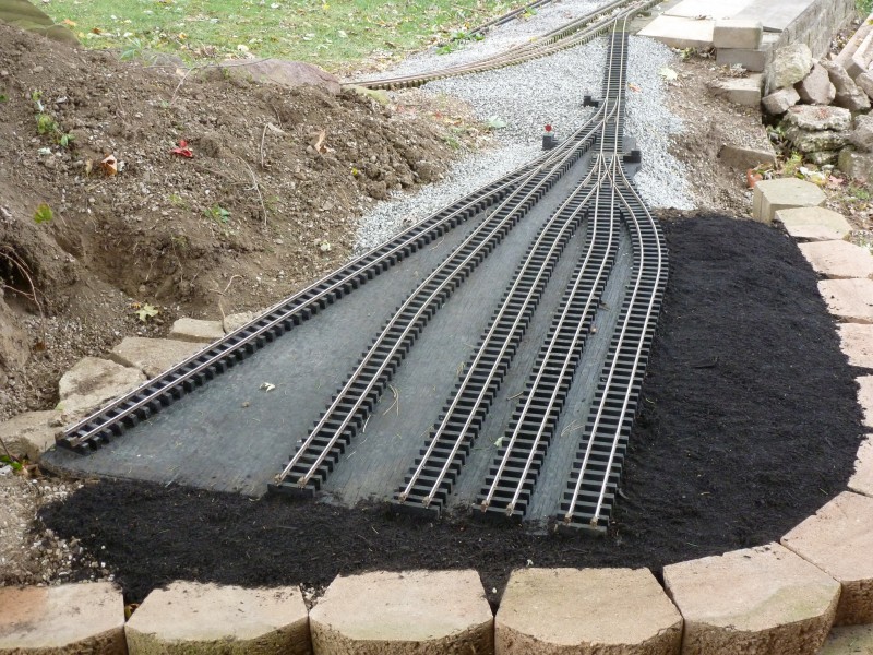
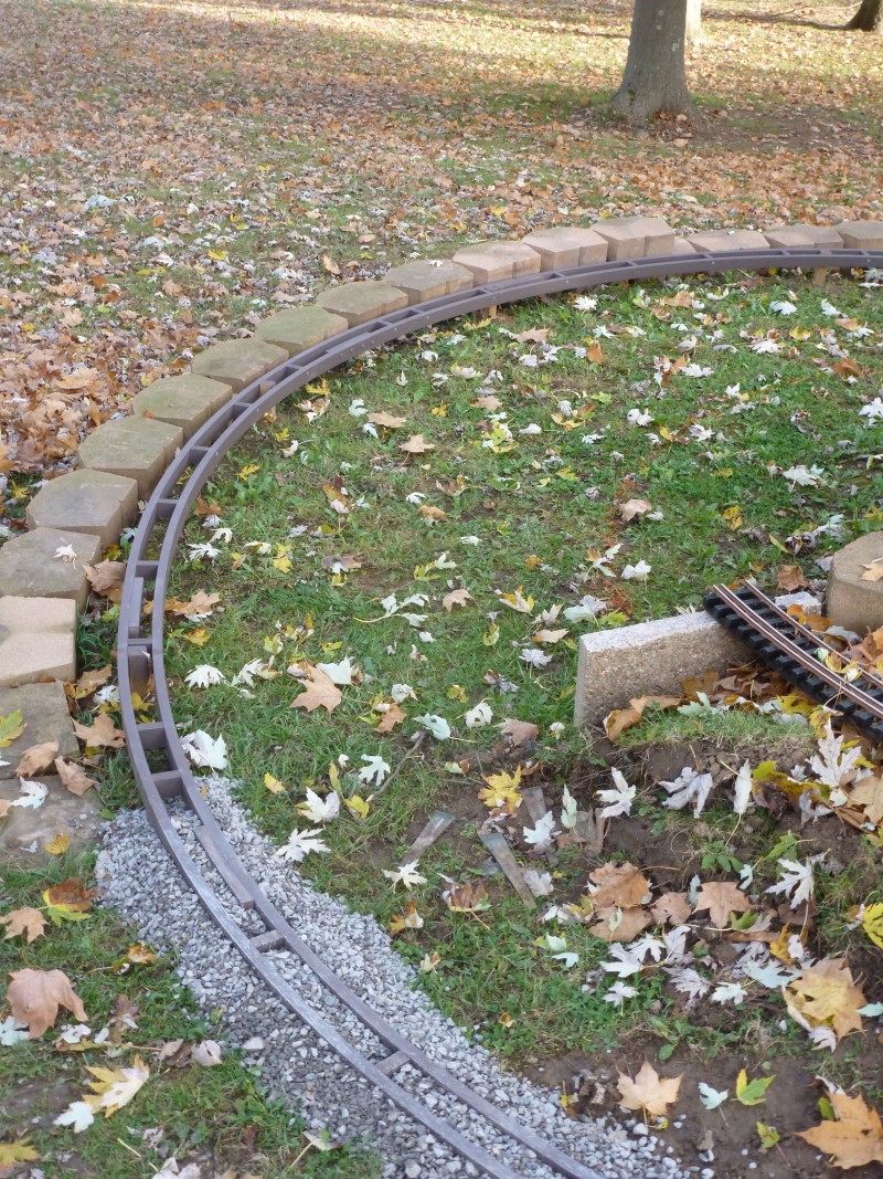
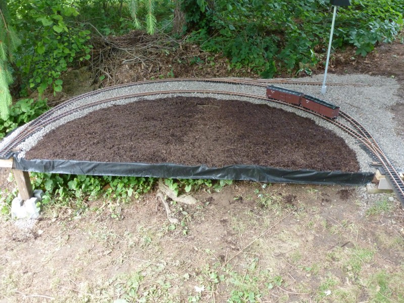
After
being back filled and connected back to the mainline the area was
mulched.
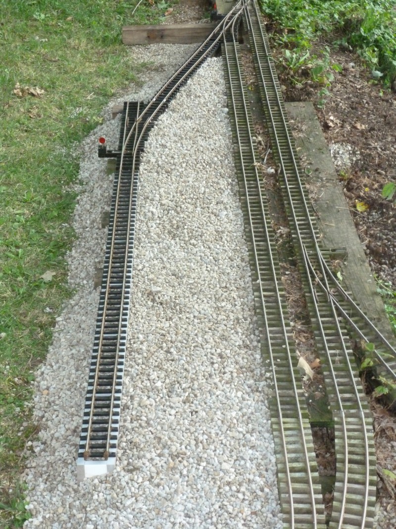
A
view from the opposite direction. Note the leaves on the ground, fall
was in the air and though there was more work that needed to be done on
the retaining wall and other things that would need to wait till the
following year.
Another
project that was done in 2014 and was actually completed ahead of the
mine track project was the addition of two sidings in the Lynville area.
The area adjacent to the passing siding was a low area that needed fill
and it looked like a perfect place for some addition industries. This
would mark the first use of ladder road bed on the layout in place of
the up to this point standard PT plywood wood base. This was at least in
part driven by the fact that reasonably flat pieces of PT plywood were
getting to be difficult to find and the fact that the solid vinyl used
in the ladder method was even more impervious to deterioration than the
plywood. At the top of the photo below a new switch was cut into the
passing siding and a short extension built to provide room for
structures followed by a second switch. All of this was done with my
traditional materials, only the two sidings themselves were built using
vinyl ladder and commercial plastic ties.
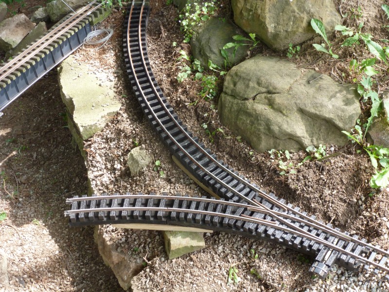
The
completed track work from both directions, note in the first photo the
disconnected lead to the mine area. These two sidings will eventually
serve four industries, a feed and grain outlet, a shoe factory, a tool
and die works and an oil distributor.
This
wasn't the only area to be refurbished and added to in 2014. The siding
off the main in Summit that serves the Ohio Valley Coal Company, a
retail coal outlet, was in need of leveling and refurbishment and I also
decided that there was some wasted space in the area that could be used
to locate an additional industry. The siding was removed from the main
switch to the point where a new switch would be added. The next photo
shows the area after removal.
The
next photo shows the refurbished track section, the new switch and new
siding. Since this area was all of the older build style the new track
work was built to match. The new siding will eventually serve Perry
Shibbels Meats.
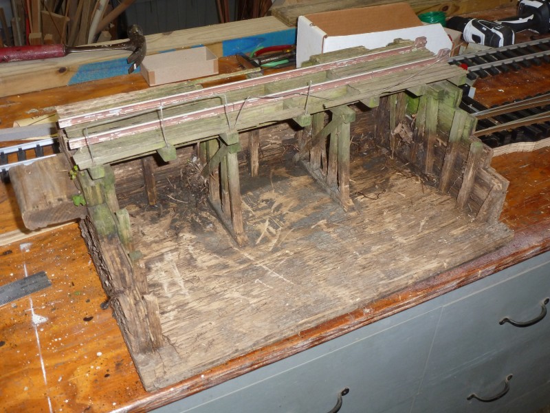
Next
to be tackled was the coal dump. Ten years of the elements with no love
had left it in pretty bad shape. Bad enough that I decided to replace
most of it rather than refurbish.
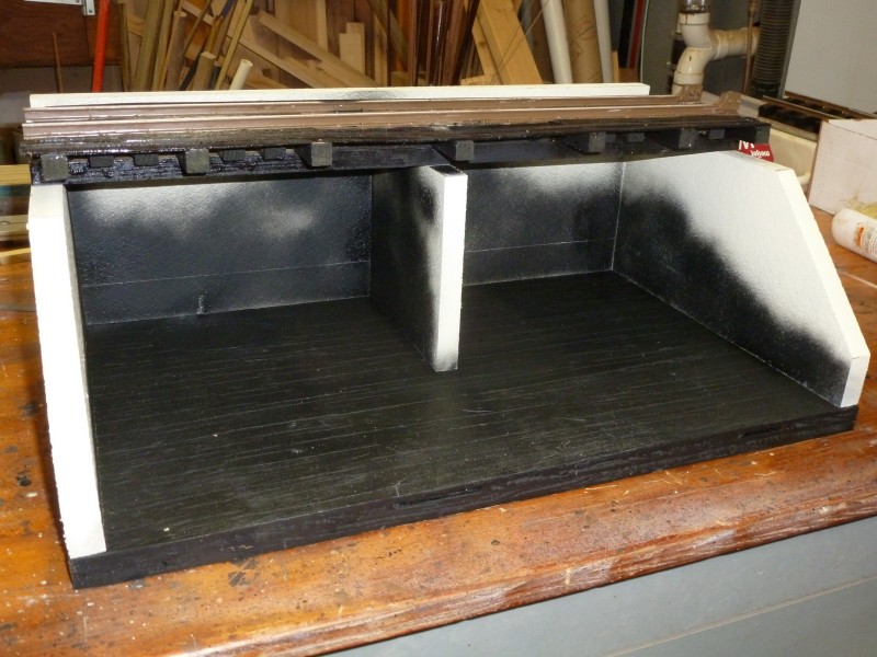
I
made a new base from PT plywood as I didn't have any plastic material
large enough to do it in one piece but this time it was thoroughly
soaked with my stain / linseed oil mixture. The rest of the pit was made
from 3/4" Trex trim board. The only salvaged part was the deck which was
re stained. The Trex parts were painted with a light tan color to
simulate a weathered concrete. The camera flash washed out the color so
it looks white. Some flat black was sprayed onto simulate staining from
the coal.
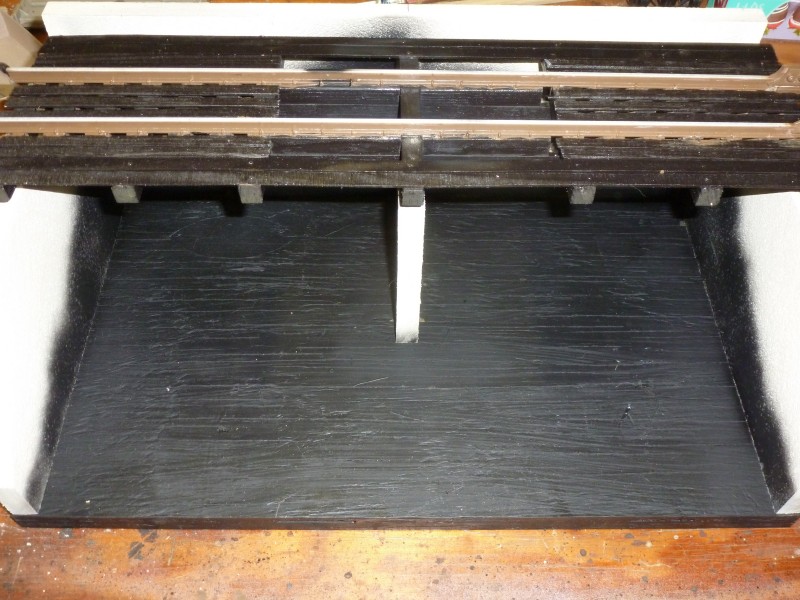
Ready
to be installed.
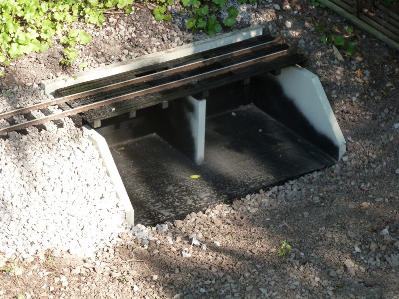
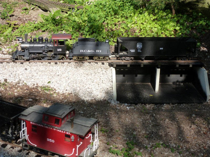
And
set in place and reconnected to the siding.
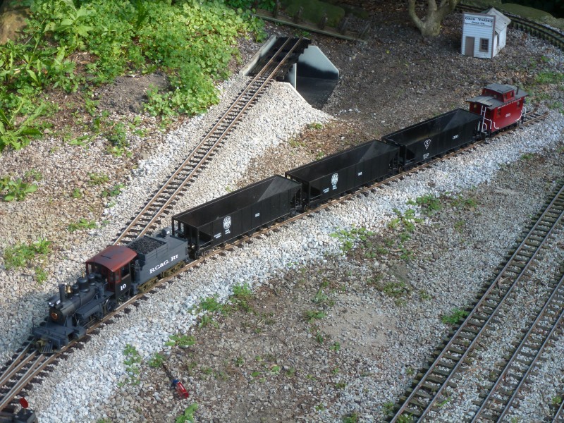
Giving
the all the track work a test we see # 10 getting ready to switch a
hopper into the coal dump.
And
spotting the hopper over the dump.
This
pretty well covers the progress made in 2014
on the layout itself and set the tone for 2015.
2015 started early in the shop. As I mentioned
earlier the first portion of the dual gauge track work spent a number
of years in a bad situation, only partially supported and exposed to
the elements the base had both warped and twisted. Fortunately some of
this could be fixed by merely soaking the plywood base with water and
allowing it to dry on a flat surface.This fixed most of the issues but
I did end up adding an additional stiffener underneath to keep
everything level. Once flattened out the switch point ties which had
originally be designed to use the Delaire switch machines were
replaced and new switch throws installed and everything was give a
good soaking coat of stain.
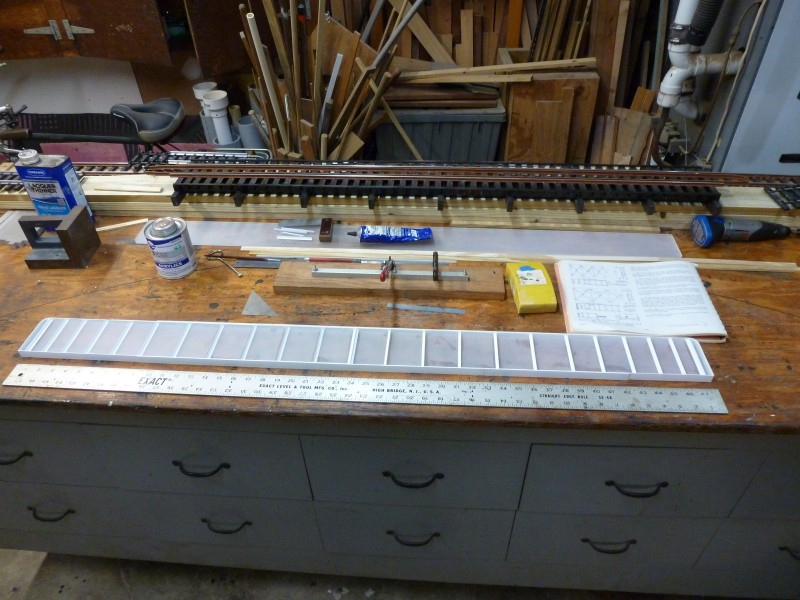
Next up was was building the almost mirror image
section that would be the other end of the interchange. Several years
earlier when I had needed to refurbish the very first section of track
installed on the layout I tried as an experiment using Trex ties. This
experiment turned out so well I decided that all future ties for hand
spiking would be made from Trex. While they don't stain well the
natural gray color looks a lot like old ties especially after they get
dirty. The best thing about them is that I was no longer plagued with
spikes popping up like I had a lot with the pressure treated ties. So
when I started on the last big piece of the standard gauge interchange
I went with the Trex ties. I went with 1/2" by 3/4" on the ties as it
save an addition rip cut. While it doesn't provide the same depth as
the original wood ties I think it will be OK as I now coat the upper
surface of the PT plywood where used. I used a PT plywood base for
this section because I still had a flat piece that was well seasoned
and dry and I like to keep multiple switch installations all on the
same base. The photo below shows the base with ties installed. These
are fastened down using stainless steel finish nails under the area
covered by the rail base and installed with an air nail gun.
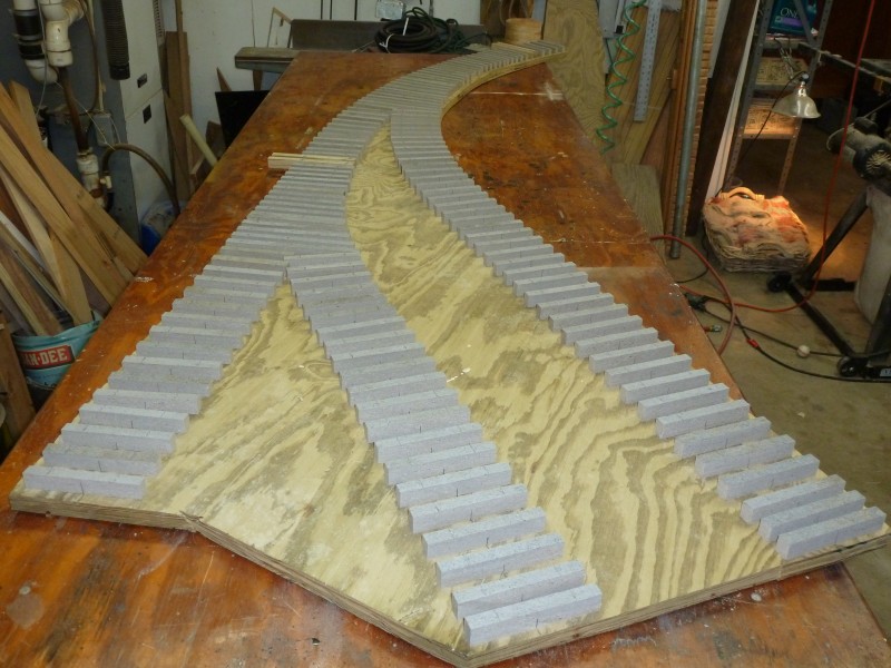
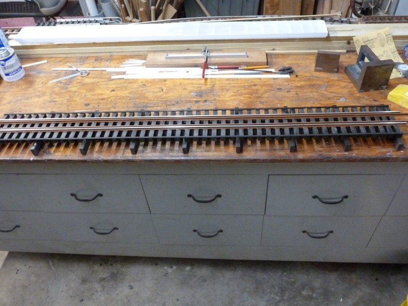
The
next three photos were taken during assembly of this section.
Mean
while out on the layout, the photo below shows where the dual gauge
interchange starts and a continuation of the retaining wall which will
hold the fill for the area that will be known as Union. The lumber to
the left is a portion of a tunnel which will be discussed later on.
In
the next photo both ends have been set in place to begin laying out the
area and to determine the length of the interconnecting sections.
At
the other end the approximate position of the standard gauge branch is
located.
A
view from the other end. The track locations marked with paint to the
left will be the interchange sidings the outer being standard gauge and
the inner narrow gauge.
'
I
needed to build a standard gauge switch to complete things and that is
show below.
And
this is roughly where it fits in.
The
stacked block retaining wall for the Union area was extended then I
started fitting the pieces together starting at the current end of the
line.
In
the next photo the wall has been completed as far as the tunnel
entrance.
The
next photo looks back up the main line and shows the mine track work and
the two new sidings added to the Lynville area that was done in 2014.
The patio blocks to the left of the tracks will be where the business
district of Lynville will be located.
And
a photo of the first section from another direction.
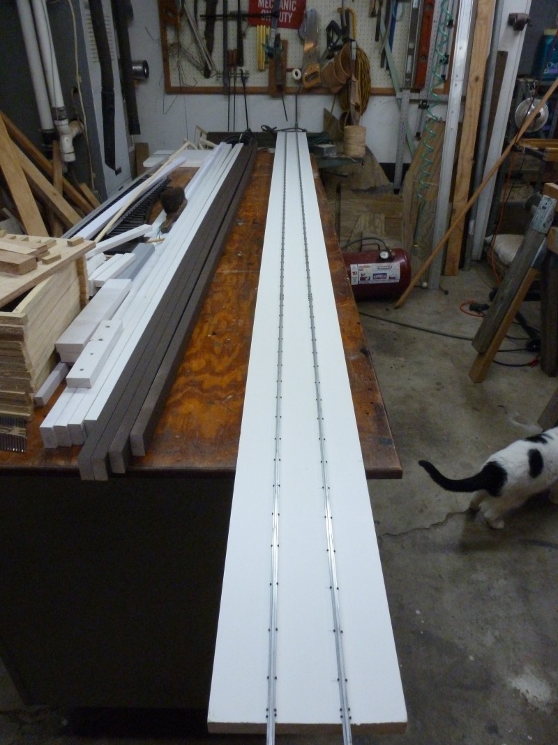
Before
anything else could be put down I needed to build up the interconnecting
track sections once I determined their lengths. The dual gauge sections
needed to be hand spiked and for the first time the ties were attached
directly to the ladder rails and the rails were then spiked down. With
the ladder rails being vinyl, the ties Trex and the spikes stainless
steel these section should be maintenance free for a long time. The
narrow gauge section was built using commercial plastic ties which were
attached to the vinyl ladder rails at approximately 6" intervals with
screws. For those interested, in 1/24 scale gauge 1 track scales out to
42". That's why the dual gauge may look strange to those in the know.
Most dual gauge track is 36" and 56" with a difference of 20" between
the two closest rails whereas here there is only a 14" difference. In
1/24 scale standard gauge figures out to 2 3/8" in round numbers.
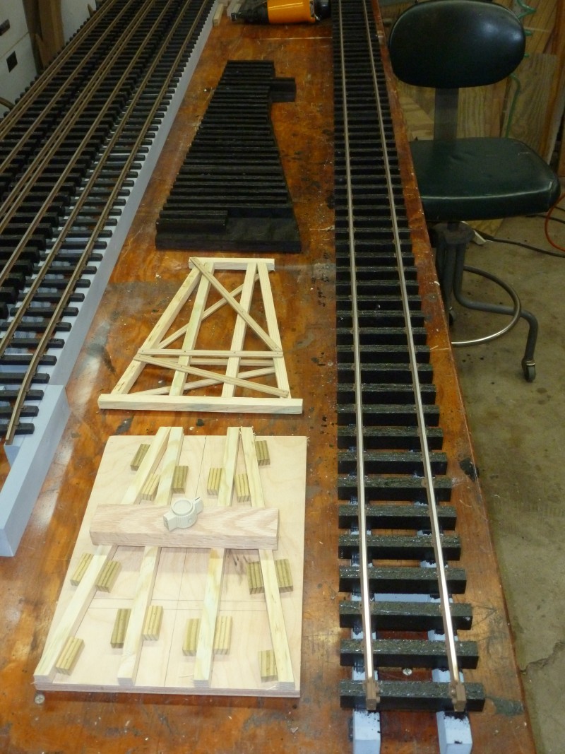
The
next photo shows the length of standard gauge track which will be used
at the gauge change area. At the bottom is the fixture for making
trestle bents that will be needed later in the year.
The
retaining wall was finished and the various pieces put in place.
A
view from the other direction.
The
last section fell just short of the abutment where the trestle approach
to a bridge that will cross over the standard gauge line starts.
A
view from the opposite direction.
A
short section was built up to extend it to the abutment and that would
end the progress on the mainline for 2015.
We
had an extended stretch of seasonable weather that lasted into early
November, as can be seen by the amount of leaf drop on the ground, and I
took advantage of this to work on the standard gauge line. The first
thing I needed for this was an end point to work towards. Mention was
made earlier about a tunnel so I will explain that now. Early on it was
decided that the standard gauge line would only be minimally modeled so
the line exits the interchange traveling down hill and passing below the
narrow gauge line and disappearing into a tunnel where it would
eventually interchange with Bart Salmons West Virginia and Kentucky line
for connection to the N&W. I wanted the tunnel to be long enough to
house a locomotive and three or four cars. The tunnel was fabricated
from 12' long 2"x12" pressure treated planks, screwed and glued
together. One end was plugged then the whole thing buried which ended up
beneath part of the track work at Union as was shown earlier. It is
possible that I may end up storing the standard gauge rolling stock in
the tunnel during off season as the entrance is sealed when its not in
use. Since a tunnel that long with access from only one end is inviting
disaster I needed to be able to be able to extract the track in a worst
case scenario. This was done by spiking rails to ten foot long section
of vinyl trim which would fit between the tunnel walls and could be slid
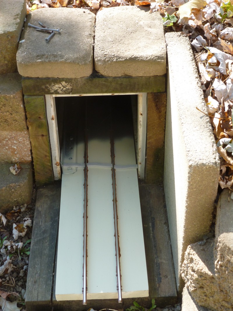
in and out as necessary. The next photo show the section after
fabrication on the bench. Not shown in the photo is a flat piece that
was added at the end to act as a bumper and to keep cars from sliding
off the end if it needed to be extracted due to a derailment.
And
below shown inserted into the tunnel. I found the section was a bit too
flexible so to stiffen it up some steel angle stock was screwed on down
one side.
With
a target in place the first thing to do was install the ladder. Again
this was made up from 1/2" x 1 1/2" vinyl trim strips. Pressure treated
balusters were used as stakes to bend the ladder around to create the
curve. The photo below shows the start at the standard gauge switch and
the next two photos show it extending all the way to the tunnel. The
retain wall was built just prior to installing the ladder. The radius of
the curve is 8'.
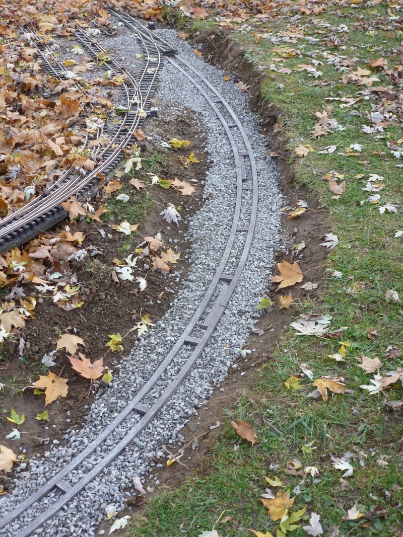
With
that in place I started spiking down the standard gauge track. This was
the most demanding hand spiking done on the layout as it had to be done
in place which meant laying on my stomach to do the first 8' or so until
the ground drops away. The next photo shows how far I got before the
weather went south for the year and marks the end of progress for 2015,
all in all a most productive year.
2016
2016
Started with building the last two dual gauge switches that would finish
the track work at Union. These are shown on the bench in the photos
below after completion.
As
in the previous years I tackled some needed refurbishment work on the
layout before adding new. The first thing done was to fix the track work
at Grinders Switch. The switch ties were newly stained and the straight
portion of the siding totally replaced with plastic ties and then fresh
ballast applied.
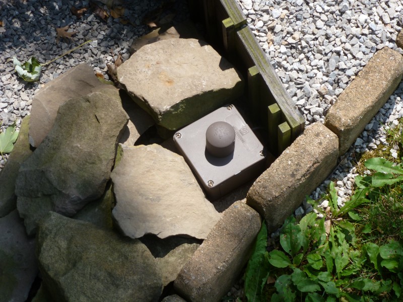
Due
to the location of this switch I decided to make it air operated so that
it would not be necessary to step over the trestle to use a manual
switch throw. To do this I used one of the old Delaire machines and
operate it from an air toggle switch. This was mounted in a sealed
electrical box and the toggle handle is protected by PVC pipe cap and is
situated near the edge of the layout as shown in the photo below. It
gets its air from the compressor in the garage which is piped to the
area beneath the power house at the engine facility and from there is
buried to the switch control box and to the switch itself.
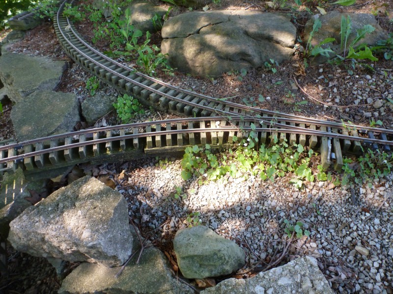
The
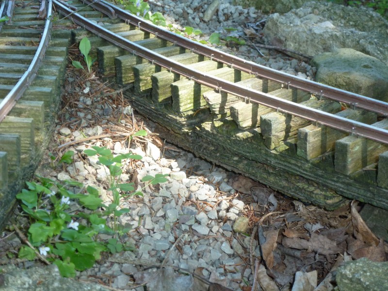
next area to get some needed attention was the Kitty Wye. This area has
always been only partially finished at best as it can't be properly
completed until a water course (AKA Raccoon Creek) is completed from the
grist mill to the Ohio River. This meant that again substructure that
should have been covered from the sun by fill and ballast was not and
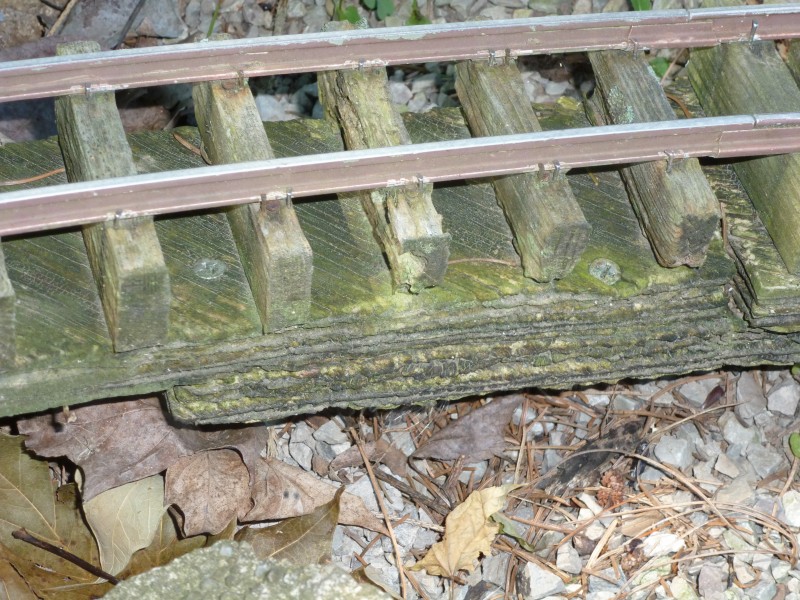
time took its toll. The next three photos show show the wye switch
itself and surrounding track and close ups showing the deterioration.
Note
the multitude of popped spikes which was common with the solid wood
ties.
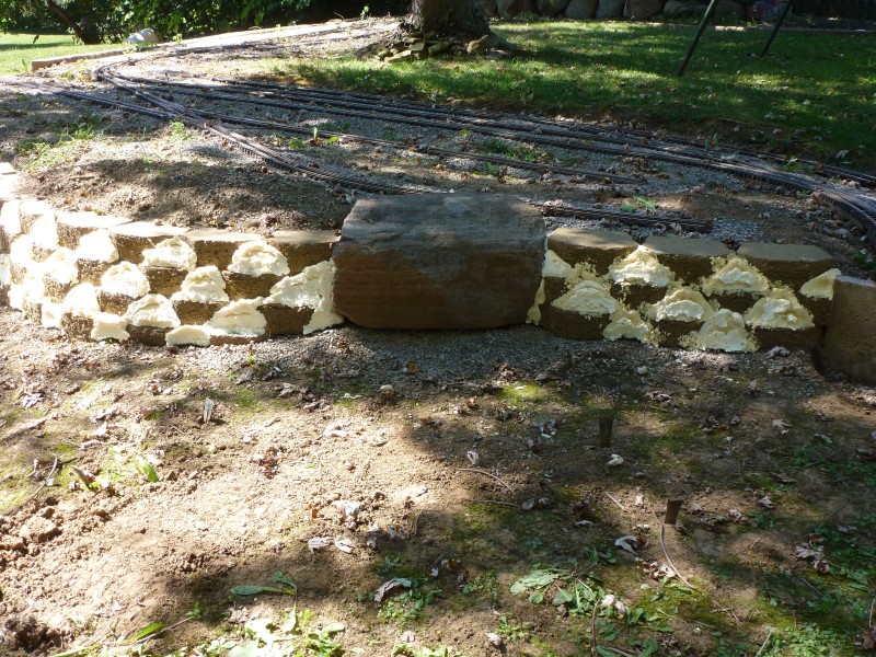
Some
slabs of an old broken up side walk were used to build up a retaining
wall on one side of the gully allowing more of the substructure on that
side to be covered.
The
wye switch and two leads coming off of it were rebuilt using Trex ties
and some of the PT roadbed was replaced as well. The wye switch retained
its air operator as this switch will be automatically triggered by
trains heading down hill. The method for this will be discussed
elsewhere.
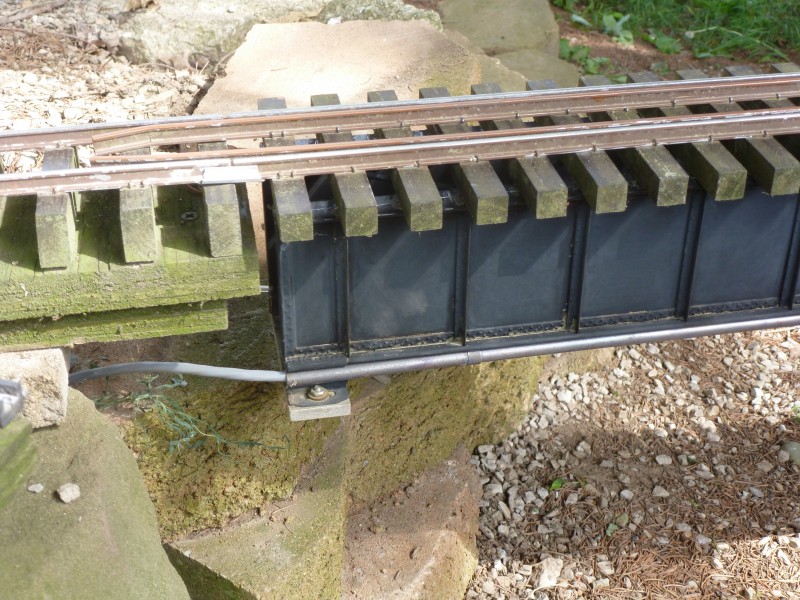
As
part of this control for this I needed to get both an air line and
electrical line across the Gully at this point so two brass conduits
were fabricated and attached to the bridge. The next photo shows conduit
at one end with the electrical cable coming out of it, there is an
identical one on the opposite side with an air line running through it.
This detail is commonly found on prototype bridges carrying water, gas,
electric or communication lines across bridges.
The
next photo shows the area after it was "refreshed", there is still much
to be done here but it won't be done until I finish the work on the
water feature.
With
that out of the way attention was again turned to the dual gauge
interchange where the last two switches for the area were installed. The
next four photos show the installation in progress and completed from
both directions.
In
the above photo the two sidings in the foreground will service the brick
plant and the one in the background the tannery.
Work
also continued on the standard gauge line, ties first then with rail
spiked down.
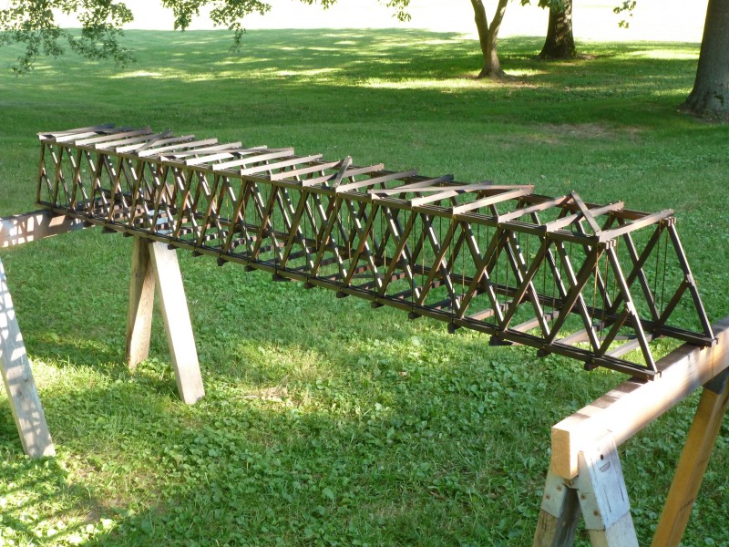
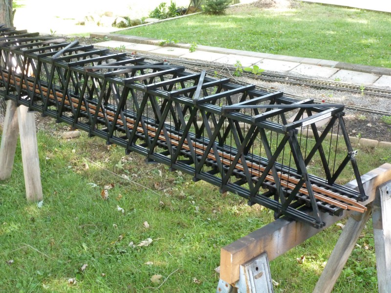
During
the winter about two years earlier I fabricated the bridge that the
narrow gauge would use to span the standard gauge line. Constructed
entirely from redwood it was built from plans posted here
on George Schreyer's website and is a close in design to a Howe Truss
bridge and it's support system functions as the prototypes did. It was
stored until needed. It was going to be needed soon so this summer it
was brought out from storage and given a coat of my standard stain. The
photo below shows it before staining.
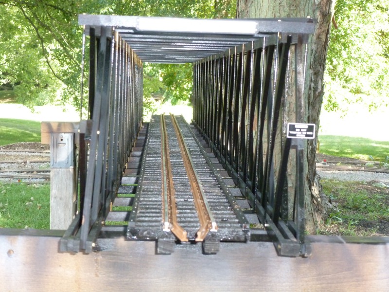
It
still needed the bridge deck built and rails installed and the next
photo shows it after it was installed and the bridge after staining.
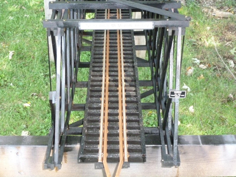
A
view from a different angle. The camera wouldn't focus on the lettering
on the sign mounted on the top beam. The bridge is named the "Tiny
Pierce Memorial Bridge" for a deceased friend and fellow garden
railroader who passed too early from complications of diabetes. He liked
bridges and had many different kinds on his layout.
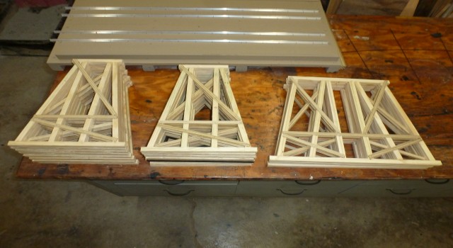
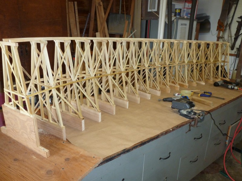
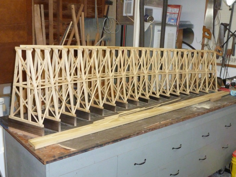
In
order to get from the current end of main line to the point where the
bridge needed to be located a curved trestle needed to be built. The
photo below shows the bents that were assembled using the jig show
earlier. Also there are the heavier duty doubled bents that will support
the ends of the bridge.
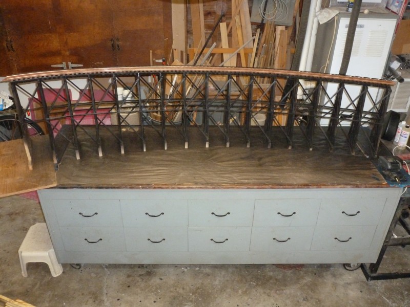
I'm
going to show how I went about laying out and building the trestle in
the articles section here. So I will skip
to photos showing the trestle after completion test fitted with the
bridge to check track alignment. Note the it was necessary to continue
dual gauge track partway out on the trestle to allow room for the
switcher room to make a run around move on the interchange.
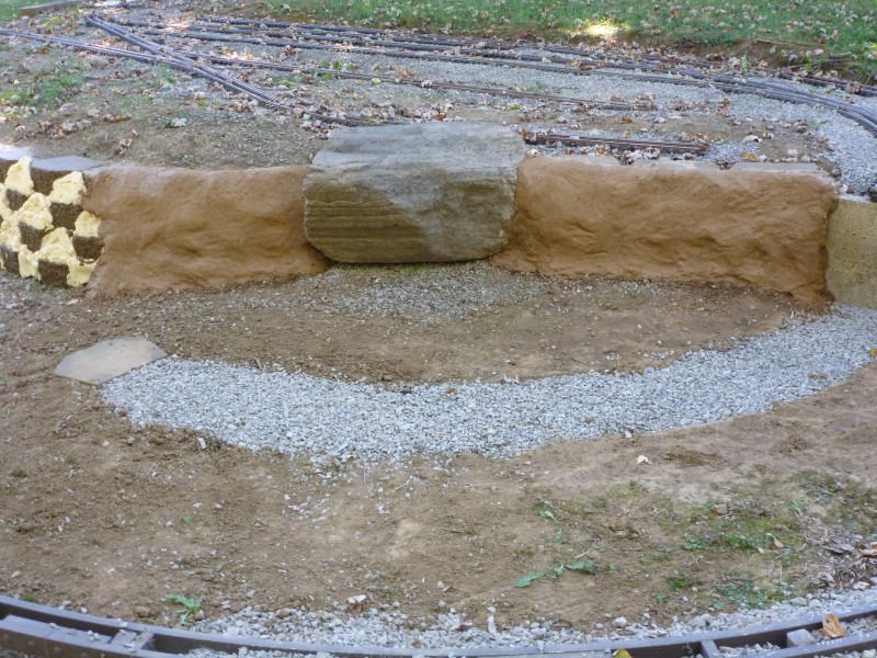
Now
some of the crazy stuff starts ! I felt that in the future that the
trestle location would be a great photo spot but I really didn't like
the stacked wall that would be in the background on photos taken there.
So I decided to do what the small scale folks do inside and build some
scenery. I had used some hypertufa on another part of the layout years
earlier and decided to do some here as well. Hypertufa is a concrete
concoction that has vermiculite mixed with the concrete. This makes it a
bit lighter and is commonly used to make concrete planters. Due to the
way the stacking wall blocks fit together there are large spaces that
would need to be filled and I felt I could save a lot of concrete mix if
I filled the spaces with foam. So Great Stuff was applied to these area
and when dry the excess was cut off using a hack saw blade free hand.
The result before application of the hypertufa is shown below.
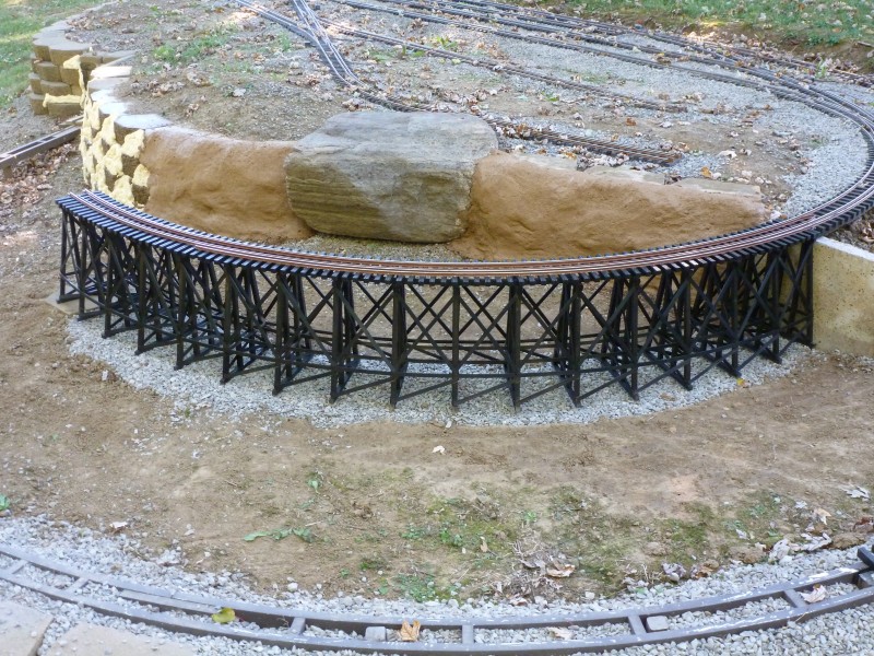
Before
applying the mixture a concrete adhesive was applied of the foam and
blocks to improve adhesion. The mixture itself was colored using
commercially available colorants and was apply by hand (wearing gloves
an absolute necessity) and allowed to cure which takes a bit longer than
normal concrete as the vermiculite absorbs a lot of water. The end
result is shown below. Certainly not perfect but to my eye better than
just the blocks. It wasn't totally cured in the photo and the color will
lighten more when it does. The idea was to simulate the sand stone that
is very prevalent in this area.
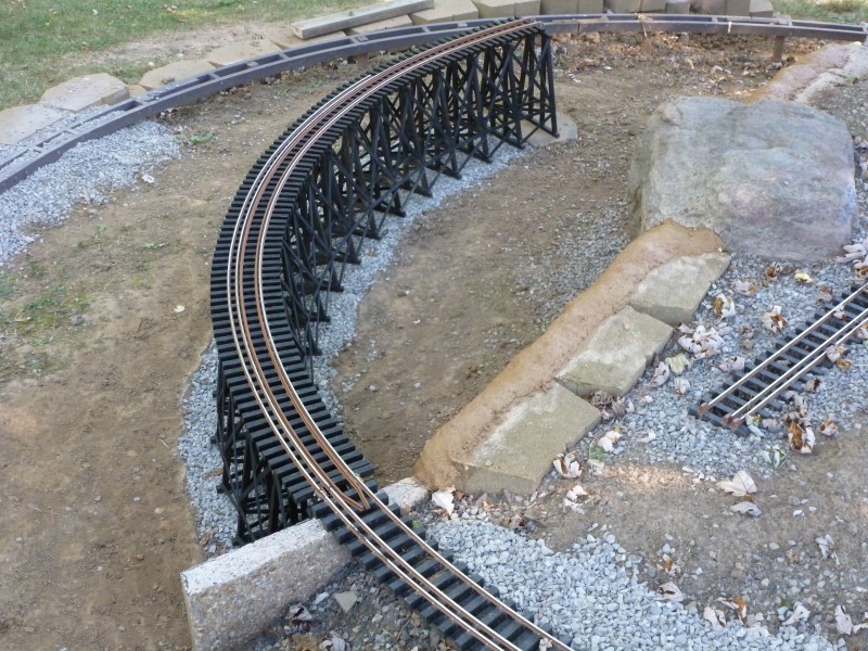
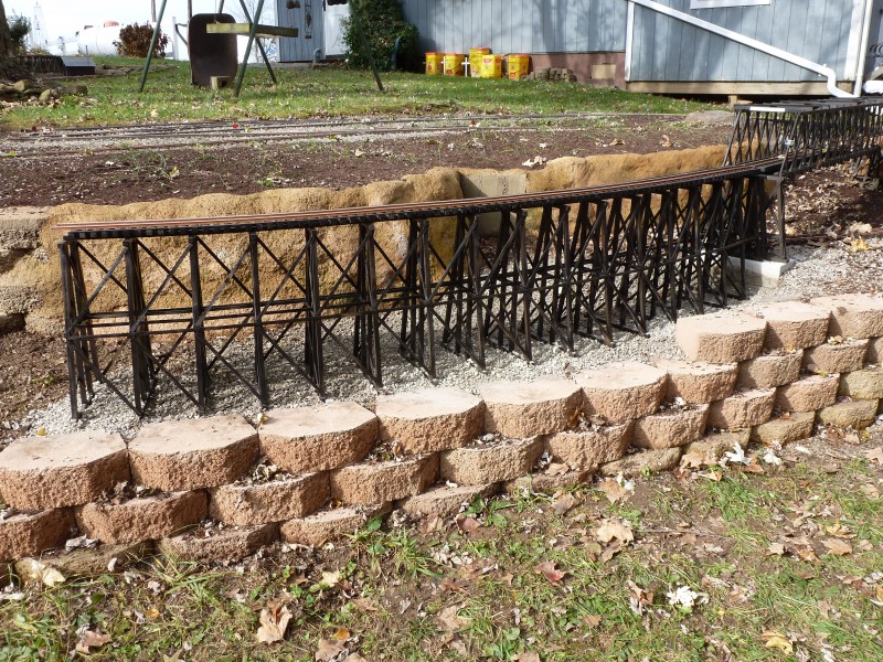
In
the next photo the trestle has been set in place, leveled and connected
to the main.
From
another perspective. Note that since the earlier trestle photo had been
taken the guard rails have been installed.
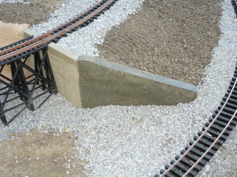
I
found when doing the fill that I needed an extended retaining wall to
better contour the fill and keep it in place. I made up some wooden
forms and cast it in place using mortar mix.
Ties
are making their way closer to the tunnel.
The
lower stacked retaining wall was lengthened to support the fill for the
far end of the bridge.
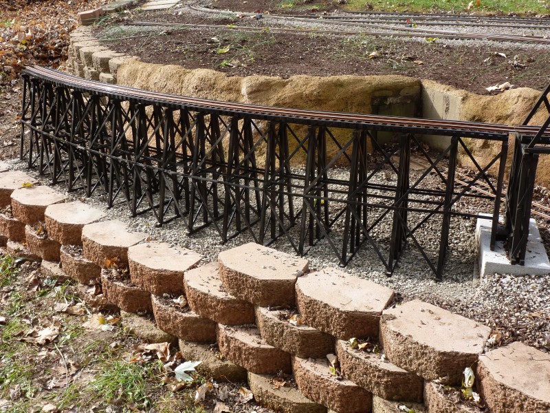
The
bridge was temporarily set in place to check alignments and level. The
entire standard gauge interchange and the track work to the end of the
bridge is one of the few level areas on the layout.
The
bridge was then removed and the balance of the standard gauge line was
installed. You can also see here that the "scenery" has been extended to
the tunnel entrance.
This
aerial view shows the state of this portion of the layout at the end of
the 2016 building season.
2017
2017
started where 2016 left off. We had some heavy winter and spring rains
and the standard gauge main was in need of some fresh fill and ballast.
Once this was done the bridge, which had only been temporarily installed
the previous fall, was permanently installed. By permanent I'm referring
to the two bridge support bents that were fastened to the concrete
blocks they are sitting on. The bridge rails are attached using Hillman
bridge clamps so that it can be removed if necessary.
More stacked retaining
wall was built to provide the necessary grade for the next section
of main. From the bridge the main needed to descend towards Paiute
Junction and unless I wanted to build a really high retaining wall
and use a lot of fill it would need to be on a trestle for the first
20 feet or so of the decent. The previous fall I had done some
survey work and determined that I would need the line to drop at a
nearly 3% grade to end up at the correct level to tie into Paiute
Junction. I did however make a mistake in this calculation that I
would not find out until to late to reduce the grade.
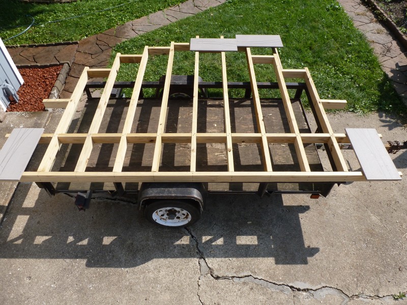
Like the tunnel was a target to build
the mainline towards I now needed a target for the mainline and this
would be Paiute Junction. At Paiute Junction the mainline would make a
180º turn. There would need to be a passing siding there as well as
the junction switch leading off to the Paiute Lumber Company. All of
this needed to be located very close to a large pine tree and the
ground where it was located was on a slope and full of tree roots. I
decided early on that trying to build this using all on ladder alone
would be an exercise in frustration. In the old days I would have used
my standard method of PT plywood but wanted to try something different
here. To keep the weight down and provide a solid base for the
switches and ladder with the interconnecting track work I decided to
go with an open frame made from PT 2x4's. I constructed the frame work
on my trailer to make it easier to transport to the job site. The gray
rectangles are the Trex bases for the four switches involved. To
increase the rigidity of the frame I used half lap joints on the
second from the front cross wise 2x4.
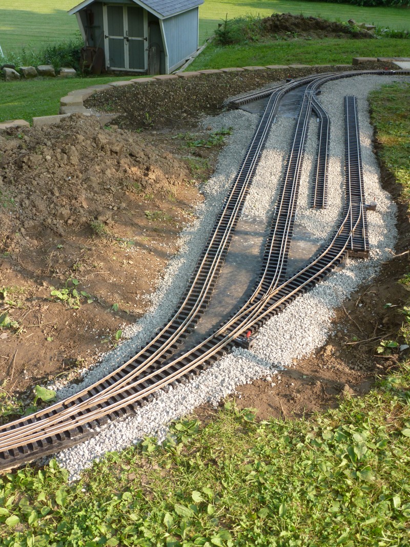
The next three photos show just how
uneven the location for this was. The first two photos show it in
place and roughly leveled.
The next one shows how it ended up.
Deck blocks were used on the high end to provide a solid foundation.
The other end sits on patio blocks that have been set into the ground
and pinned to keep them from moving.
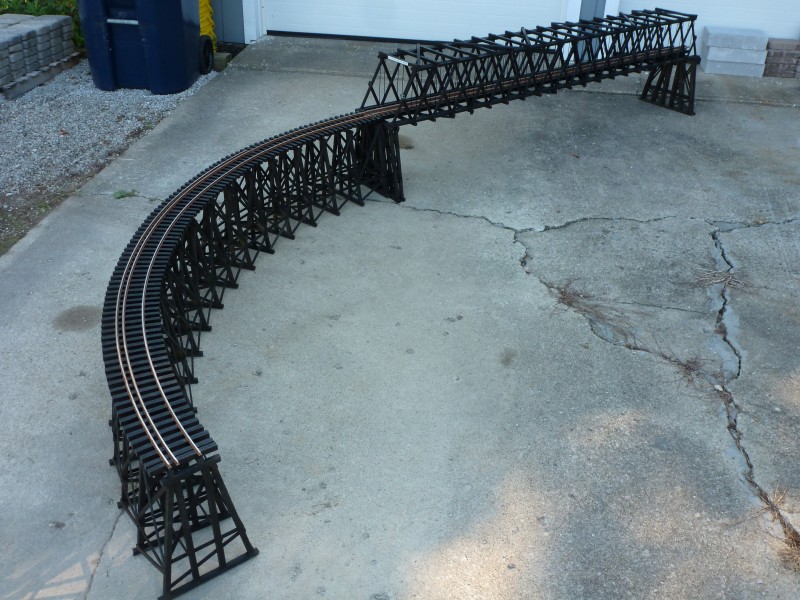
With that in place the next task was to
build the trestle that comes off the bridge. This needed to be built
on a 3% slope, or so I thought. It was laid out much like the previous
trestle described in the articles section. The primary difference was
adding descending spacer blocks under each section. The first photo
shows it ready for stain and the following one stained with ties and
rails in place and ready for the layout. The trestle is built on a 12'
radius curve and this section is only the first of two required to
make the required turn to align with Paiute Junction.
The first section installed.
And from a different angle.
And an overhead view. The leaves on the
ground signal the end of another building season. Not as much
accomplished but a lot of heavy work slowed progress.
2018
The goal for 2018 was to finish the
mainline track work so I could concentrate on other aspects of the
railroad but in the end it was not to be. We had an over abundance of
rain and ended the year with a record amount of rain fall. This had
two effects on construction. For one all the extra rain kept the grass
growing at a record pace meaning I was spending way more time mowing
and the extra rain made the area that I needed to work in muddy and
difficult to work. Work again started in the shop where the next
section of trestle for the mainline was built using the same method as
used on the first section.
The
next photo shows the finished next section installed. Of note I found
out when I went to install this that it ended up too close to the
retaining wall and didn't line up well with Paiute Junction so a short
straight section was built and inserted between the two curved sections.
An inelegant solution but it worked.
A
view from the opposite direction.
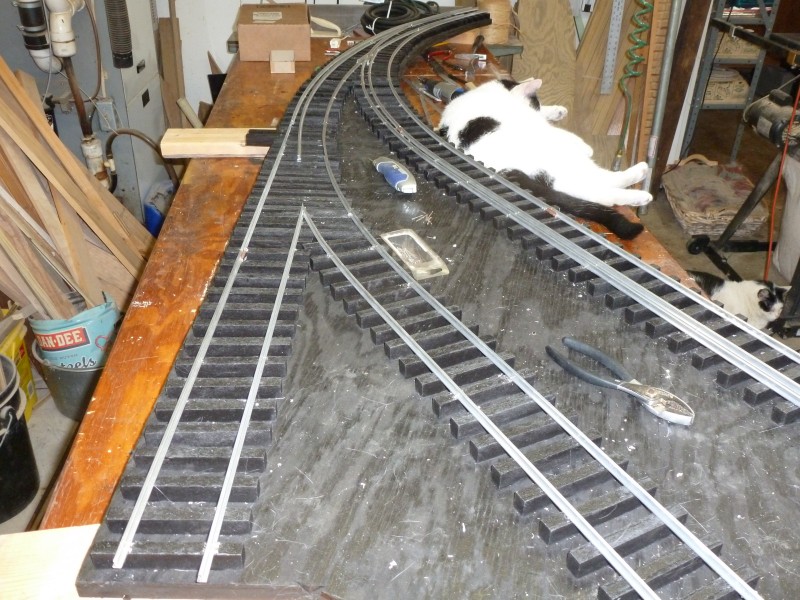
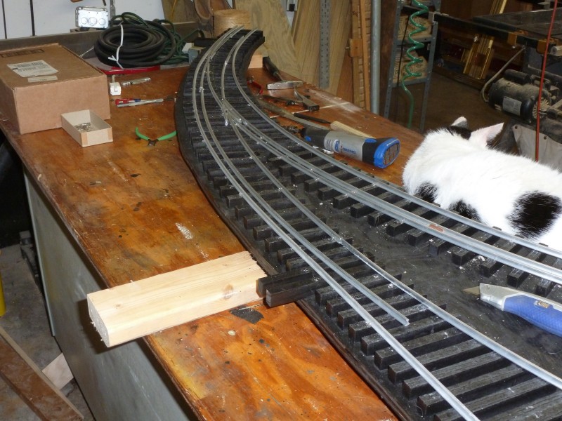
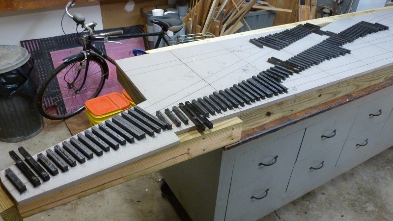
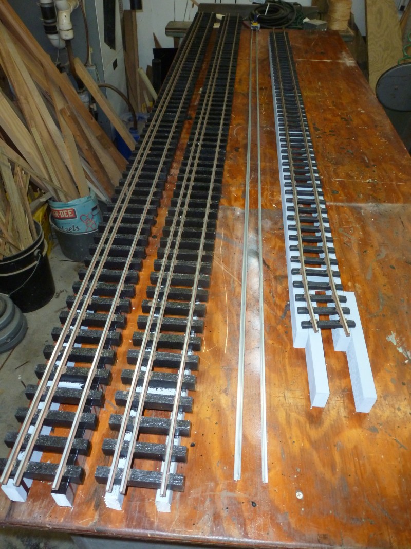
Mean
while, back in the shop the track sections for the track work between
the end of the trestle and Paiute Junction were assembled. This is just
commercial flex track with a difference. To better blend it in with my
hand laid track work the tie strips are cut apart and the tie spacing
increased. This is done utilizing the jig at the far left on the bench.
It has dado's cut in it, ties are set in place and the rail threaded
through them. Once set the rail is painted its rust color using a
generous amount of paint to glue the ties to the rail keeping them in
place until it's attached to ladder frame. Also in the photo can be seen
the four switch blocks for Paiute Junction that have been removed from
the frame to build the switches on them.
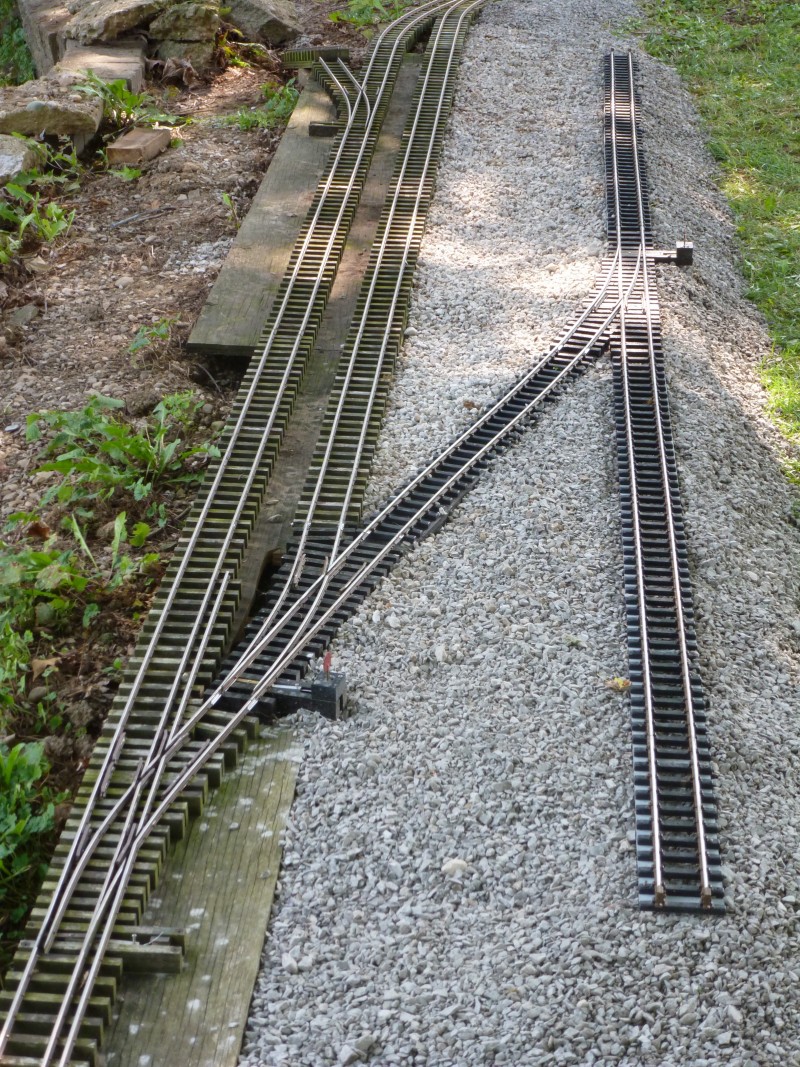
One
last short section of trestle was needed to finish it off and eliminate
more retaining wall. It was at this point that I realized the error I
had made in surveying the previous year. Paiute Junction's frame raised
the end point by nearly 6" which would have allowed me to use a lesser
grade and by the time I got to the end of the trestle I had actually
dropped below the level I needed which necessitated a slight incline
between the end of the trestle and Paiute Junction.
A
slightly different angle shot.
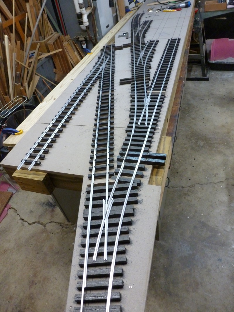
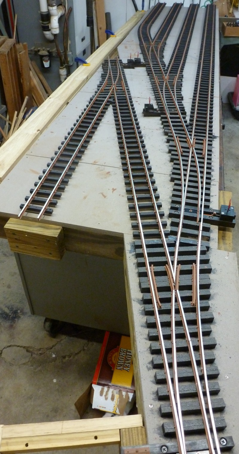
In
the next photo the four switches for Paiute Junction have been
completed.
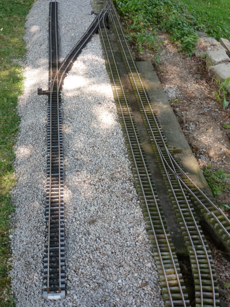
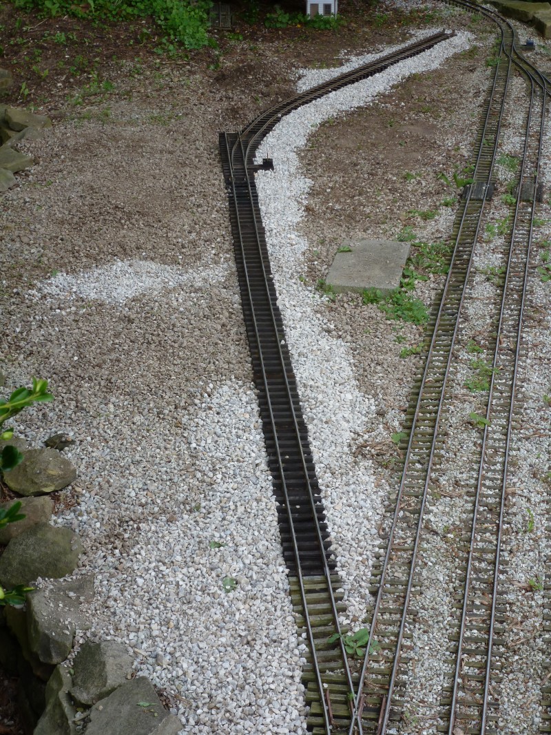
The
ladder frame was assembled and installed to tie into Paiute Junction.I
intentionally let this wander a bit as I think it looks more natural
than dead arrow straight track. This area will be filled to the level of
the track work once some additional retaining wall is built.
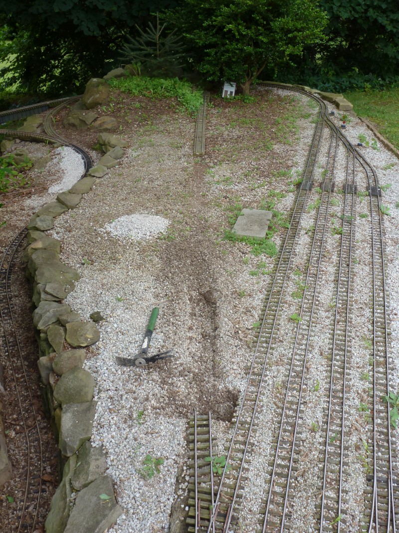
I
didn't take any in progress photos of Paiute Junction during the build
process and the next photo shows
it
finished. The bare frame was covered with 1/4" mesh hardware cloth and
then the switches and ladder connecting them was installed. Once that
was in place landscape fabric was installed and ballast and mulch over
that.
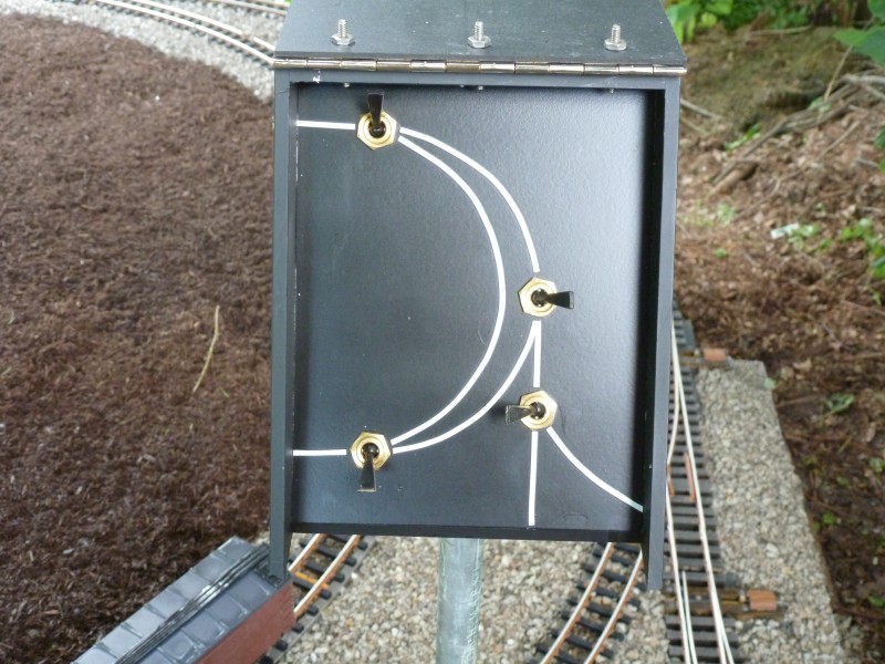
Due
to the location three of the four switches would be located in hard to
get to places so I decided early on to make them all air operated. The
panel below was made to contain the air toggles. The box was made from
1/4" acrylic. It has a plastic cover to keep dirt off the panel when not
in use. The cover uses a stainless steel piano hinge.
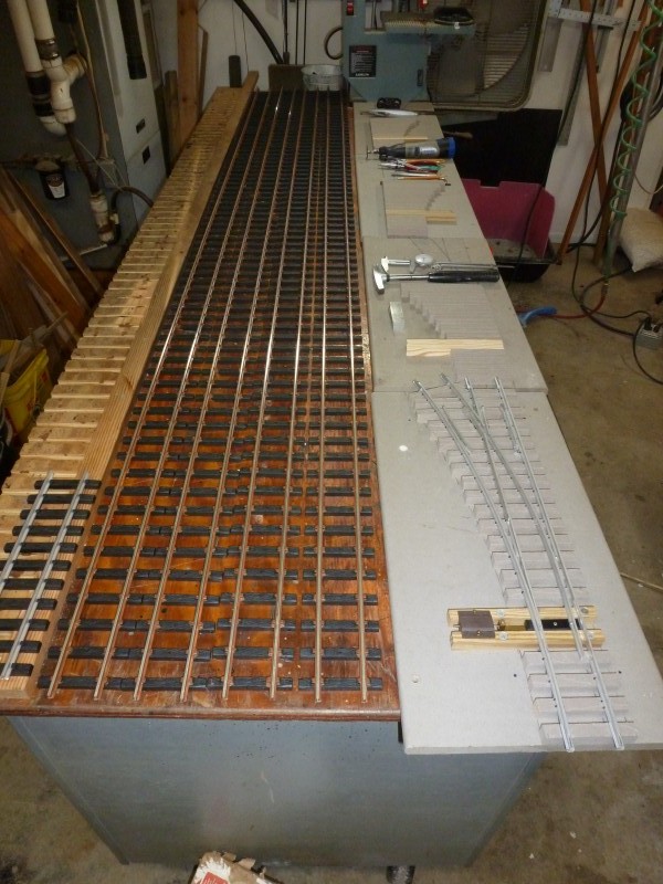
Next
up would be the target for the end of the line. This would be the yard
at Buck's Landing. again this would utilize some new techniques. A frame
work of 2x4 PT lumber was built and the upper surface covered with Trex
trim material. These were installed so as to provide the most support.
The track rail lines were drawn on and the switch ties were installed
and stained. The short lengths between the switches would be hand spiked
but all the longer lengths would be commercial plastic ties.
An
in process photo.
And
the completed section. This is approximately one half of the yard. Doing
it all in one section wouldn't have fit in the space I have to build and
would have been too heavy to move easily.
The
next photo shows it set in the approximate location it will need to be
and temporarily leveled to keep everything flat and true. It was late
September and I couldn't rely on good weather so it needed to be solid
for the winter.
The
second half frame was built and the track plan penciled in. It is shown
in the next photo set in place to allow for holes to be located to
fasten the two sections together once the second half is completed. Once
this was done the second half was returned to the shop. As it turned out
shortly after this was taken the weather again turned rainy and little
else was accomplished after this.
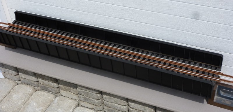
The
only other project to be completed during 2018 was replacement of the
deck girder bridge spanning Raccoon Creek at the Kitty Wye. The bridge
was going to create some issues when I get around to building proper
abutments for it and I had another place I wanted to use it so a new
through girder bridge was fabricated. The side girders were made from
1/4" thick acrylic to which a lot of angle stock was added for detail.
The bridge was based on an actual prototype that was illustrated in
Frank Armstrong's Bridge and Trestle Handbook.
Next
photo shows the bridge deck which was made from PT strip wood with Trex
ties and the rail hand spiked.
The
finished bridge from the top
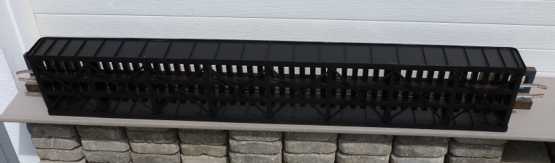
And
the bottom.
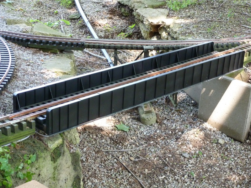
Next
photo show it installed. I removed the conduits carrying the electric
and air lines from the other bridge and attached them to the new one.
Another
view.
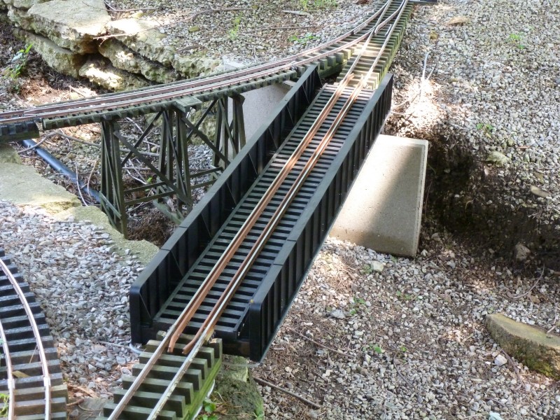
And
with # 7 crossing it with a train.
A
fair amount completed but still short of goals. Hope springs eternal
that 2019 is a dryer and more productive year.
Click
here to see the 2019 WIP.