R C &
G
29
When
I went looking for photos of the earliest bits of construction of this
locomotive I came up empty handed. I could have sworn I took some but so
far no luck finding them. If I do I'll add them at a later date.
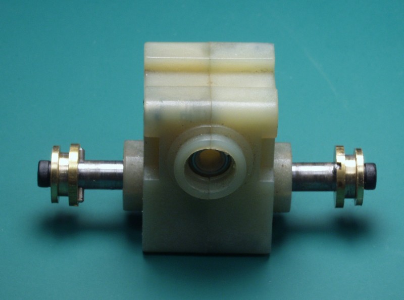
Probably
the earliest photo I found shows the extended axles that I made for the
Aristo gear boxes. It also illustrates the method I use for attaching
the drivers to the axles that allows adjustment of the quartering. I
can't take credit for the method as it is the result of some
communications I had with Barry of Barry's Big Trains, maker of the
famous bullet proof replacement drives for Bachmann Annies. He never
supplied a drawing and what you see is my interpretation of his
verbiage. Since I've never seen one of his drives I can't say how close
I came to replicating it but it works great so I'm sticking with it. The
axle is drilled for dowel pins. Note they do not need to be offset like
I did here. Their location is critical as the will ultimately determine
the gauge of the drivers when assembled. Some adjust can be made by
altering the dimensions of some of the other parts but it's no fun to go
back and machine them a second time so it pays to measure carefully and
do the math correctly.
After
the dowel pin the next piece, machined from brass, has a slot milled in
the back side of it that fits into the dowel pin and keeps it from
rotating on the shaft. The hole through the center is a slip fit. The
smaller diameter portion of this piece fits into the back side of the
driver. The length of this section is such that it doesn't quite extend
all the way to the outer side of the driver face. The last piece of the
puzzle it a brass washer that fits into a recess bored into the face of
the driver. The driver is then placed on the axle bushing, the washer
goes on next then the socket head cap screw goes next. When the screw is
tightened it clamps the driver to the axle bushing by lieu of the
fact that the center part of the bushing is slightly short of the driver
thickness at that point. While initially I wasn't sure this would be
adequate to hold the driver in quarter, so far testing on rollers has
shown it works fine.
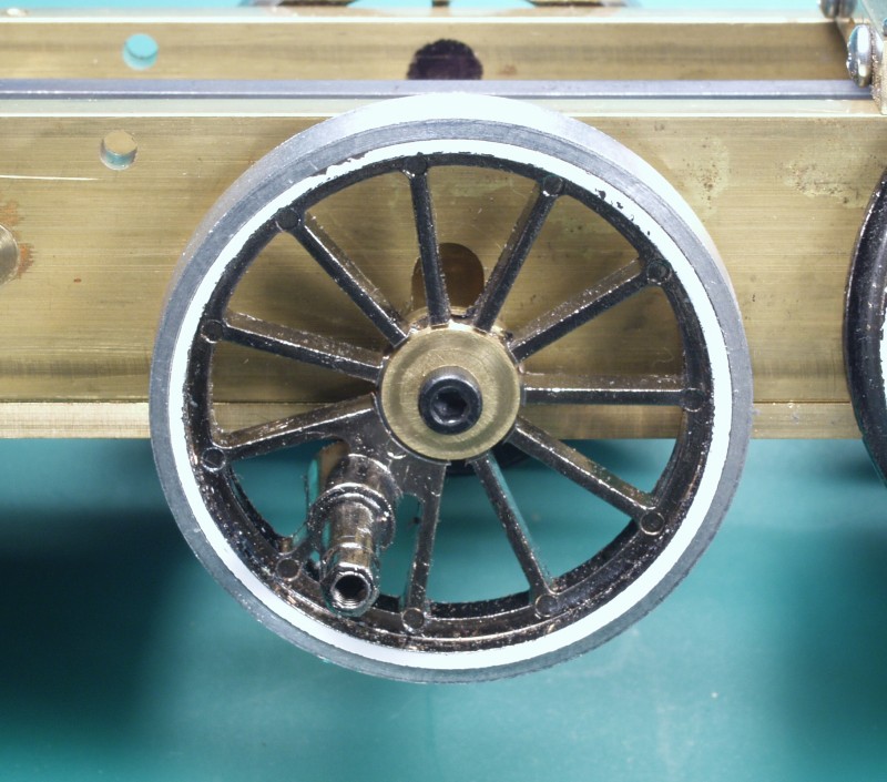
The
next photo shows the driver mounted to an axle. This is the center axle
so it doesn't have a gearbox but the plain axle is done the same way.
The clamping surface seems to be large enough to keep it from slipping
when the screw is torqued down snugly. Also note this center driver has
been fitted with an aluminum tire to bring it up to the same diameter as
the other drivers. These are from a Bachmann Annie. The center driver on
those is made smaller to help keep the others on the rails when going
over grade transitions. On this locomotive the center driver is sprung
so that is not an issue.
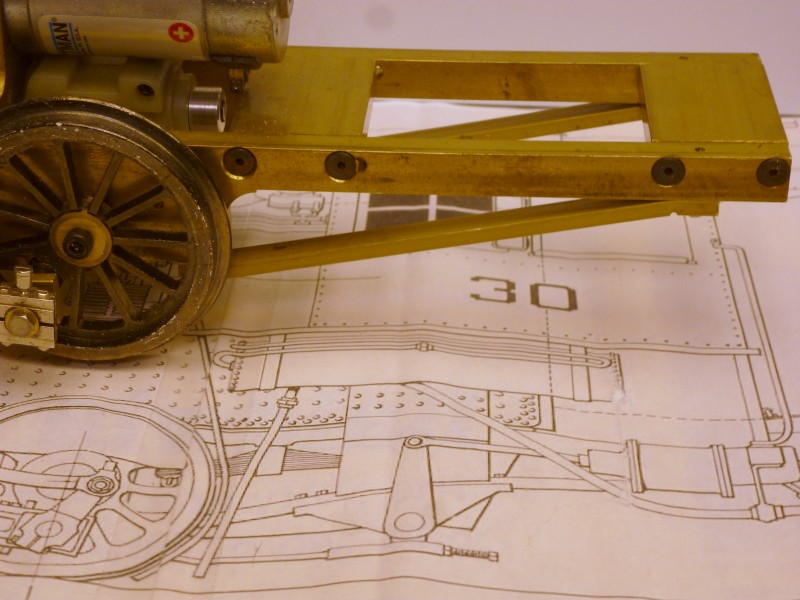
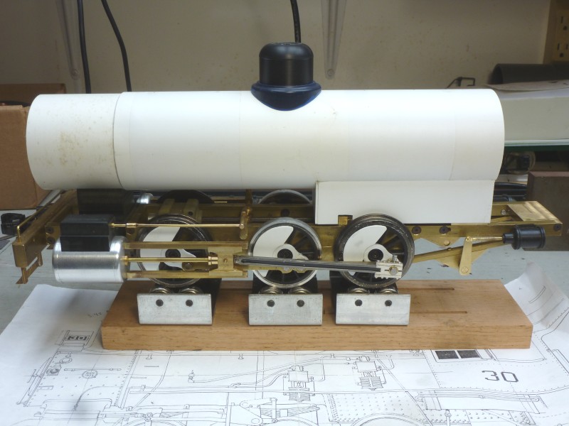
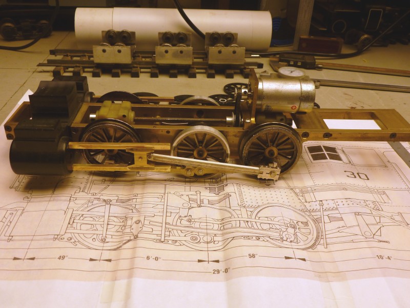
So
far this is the earliest photo of the frame I've found. At this point
the drive has been installed. Since the gearboxes have ball bearings for
the axles I just used friction bearing in the frame. I don't see this
locomotive ever accumulating a lot of mileage so they should be just
fine. The drive is similar to what I used in # 14. The two gear boxes
are tied together with a length of 4mm Allen wrench which is a perfect
fix for the hex shaped holes in the gearboxes. The frame was machined
from 1/4" brass bar stock and assembled with flat socket head cap
screws. The cylinder assembly was done similar to # 14 as well only in
this case I used Delrin instead of aluminum. The cylinders were turned
on a lathe and attached the center section. The cross head guides are
made from hollow square tubing with a short length of brass rod that
just fits inside the square tubing and is silver soldered in place. This
then fits into holes drilled in the face of the cylinder. The main rod
is from a Bachmann Annie that was beefed up by adding some styrene to
the top and bottom edges of the rod. The cross head guide was machined
from brass. The motor is a standard Pittman motor and drives the main
shaft through a timing belt. I get some additional gear reduction this
way and it provides a smooth quite drive. The frame is sitting on full
size (1/24 scale) drawing of # 29's sister engine # 30 which was
identical except for the valve gear.
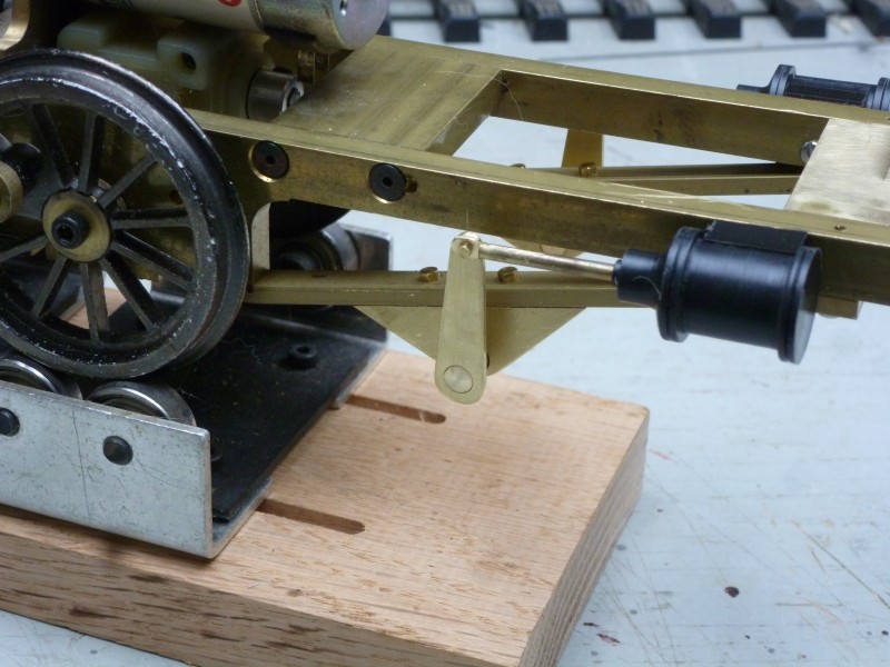
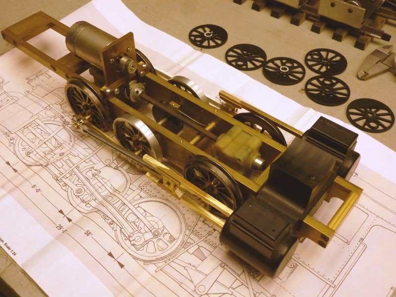
The
next photo shows a different angle. It shows the bearings for the center
axle which ride in a slot in the frame and the method I used for spring
the center driver. The round shaft between the center axle and that
front gearbox has holes drilled in it for a pieces of piano wire which
is held in place by a set screw. This wire extends back and fits into a
hole in the bearing block for the center axle, By rotating the round
shaft one can adjust the amount of spring tension on the axle. Once set
the round shaft can be tightened in place by set screws in the frame.
The shaft has a hole in it that is used to turn it to adjust the
tension. The driver centers shown behind the locomotive have had new
counter weights scaled from the drawing over laid on the original
weights.
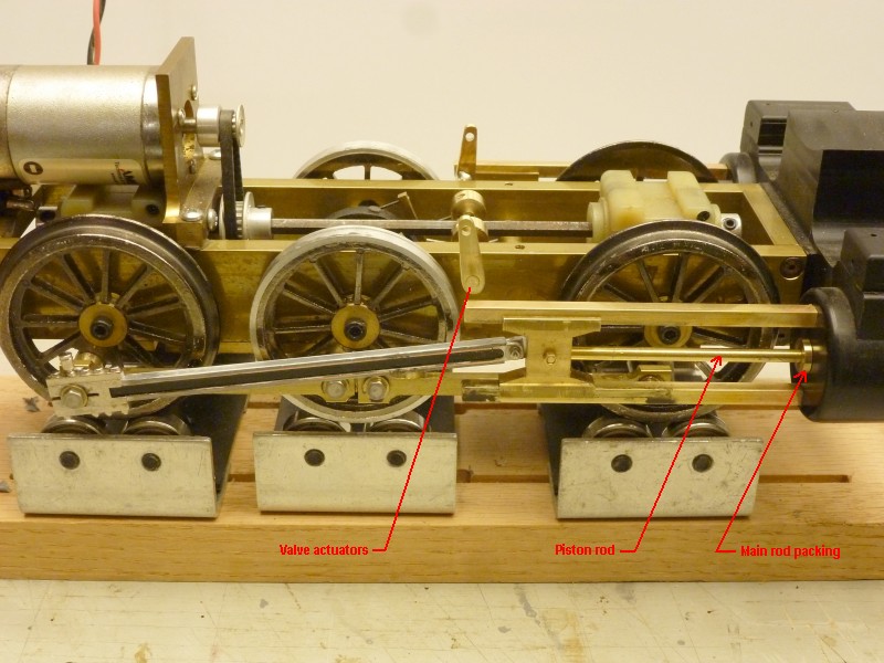
Between
the photo above and the one below several items have been added as
indicated by the red arrows. While I had no intention of duplicating the
complete Stephenson valve gear I did desire a way to add motion to the
valve actuators, something that is seldom done even in large scale.
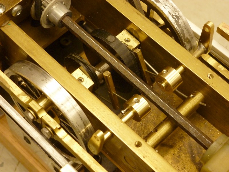
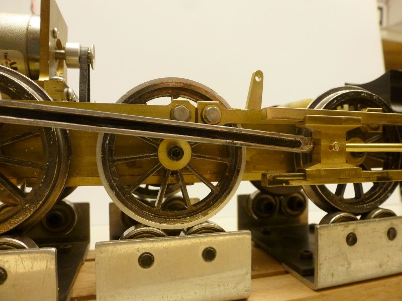
The
next photo shows how this was accomplished. Two eccentrics were turned
from Delrin and press fit on to the center axle. The eccentrics have a
groove cut into the circumference and two very simple cam followers were
made from brass bar stock and piano wire. The wire rides in the slots
and their up and down motion is transferred to the valve actuator shafts
by yet another piece of piano wire. All of this needed to take into
consideration that the center axle can move up and down. The larger
diameter disk has magnets mounted in it to provide chuff triggers.
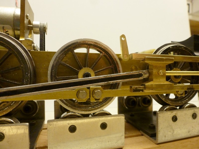
The
next two photos illustrate the range of motion of the valve actuators.
In reality not all that much but enough to provide some interest.
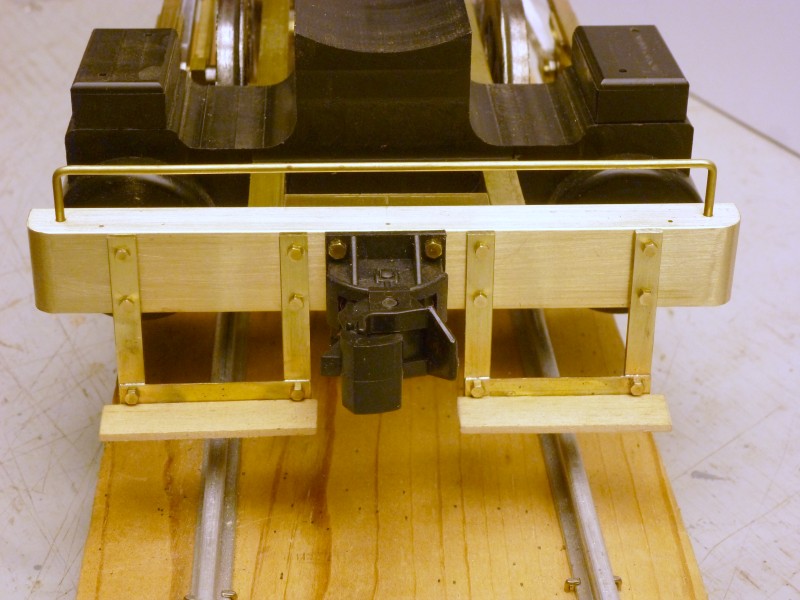
The
next thing that was added was the pilot with coupler. The pilot is all
made from brass and uses actual hex head fasteners. The foot boards are
wood.
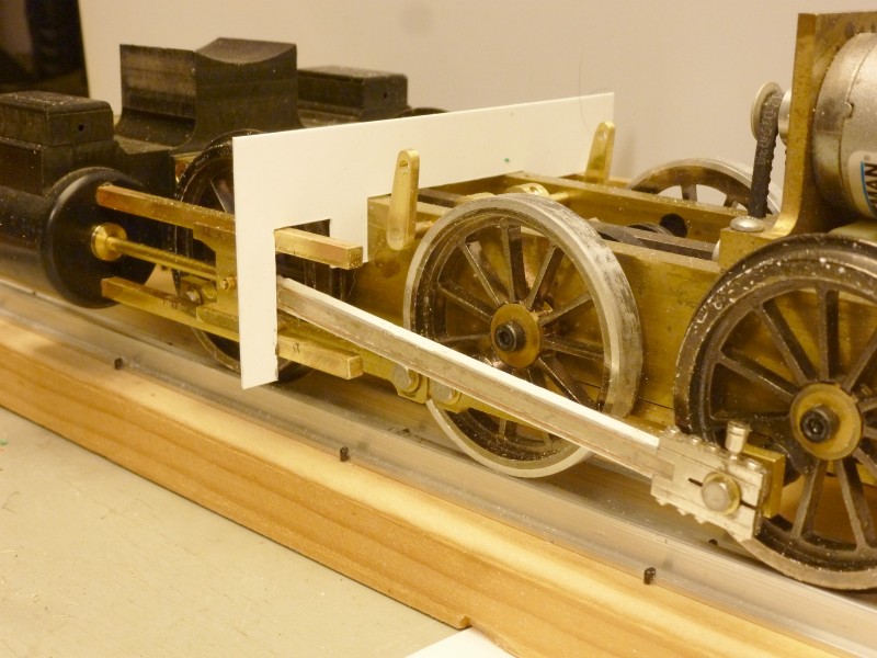
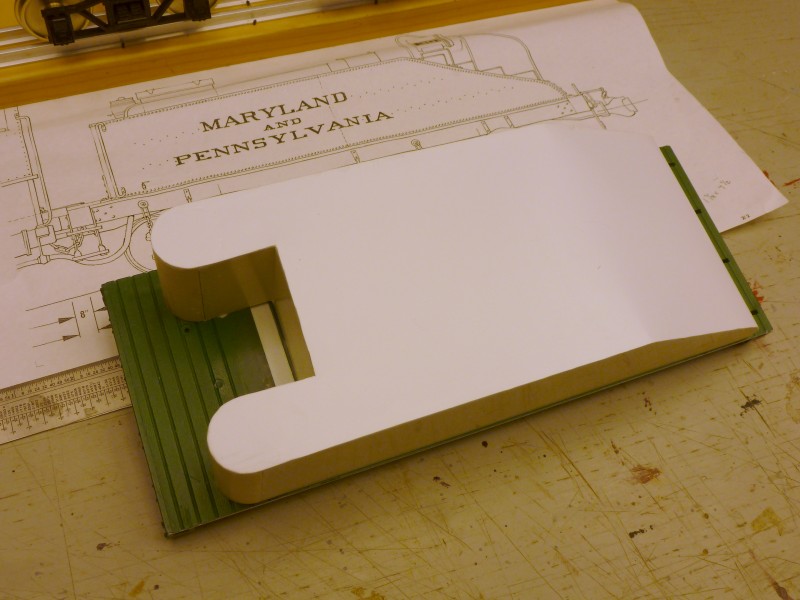
The
most current progress on the locomotive is making a template for the
mounting plate that supports the back of the cross head guides. It still
needs some additional shaping at the time of the photo.
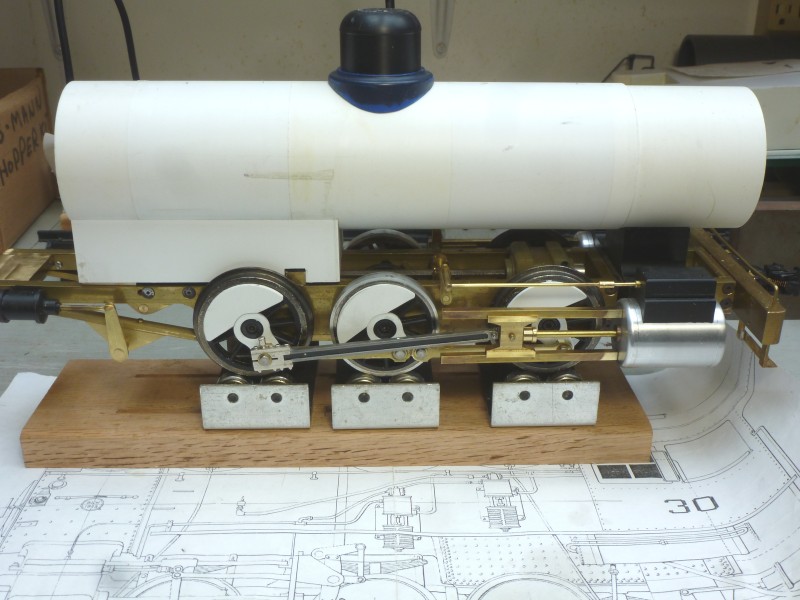
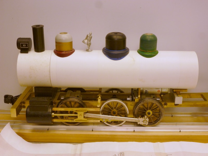
Some
basic work has begun on the boiler. The boiler is made from several PVC
pipe couplers glued together with short lengths of pipe then turned on
the lathe to level it all out and achieve the desired diameter. This was
done as the diameter I needed fell between common pipe sizes. The smoke
box will get a thin styrene overlay with rivets embossed on it. The
headlight is a stock Bachmann item, the smoke stack which still needs a
base was turned on the lathe as none of the available ones I had were
the correct diameter, shape and length. The domes are reshaped Bachmann
items. The large steam dome was turned from Delrin but the base came
from a Bachmann dome. The bell is an Ozark casting. The rear support for
the boiler is just a few pieces stacked to hold the boiler level for the
photo.
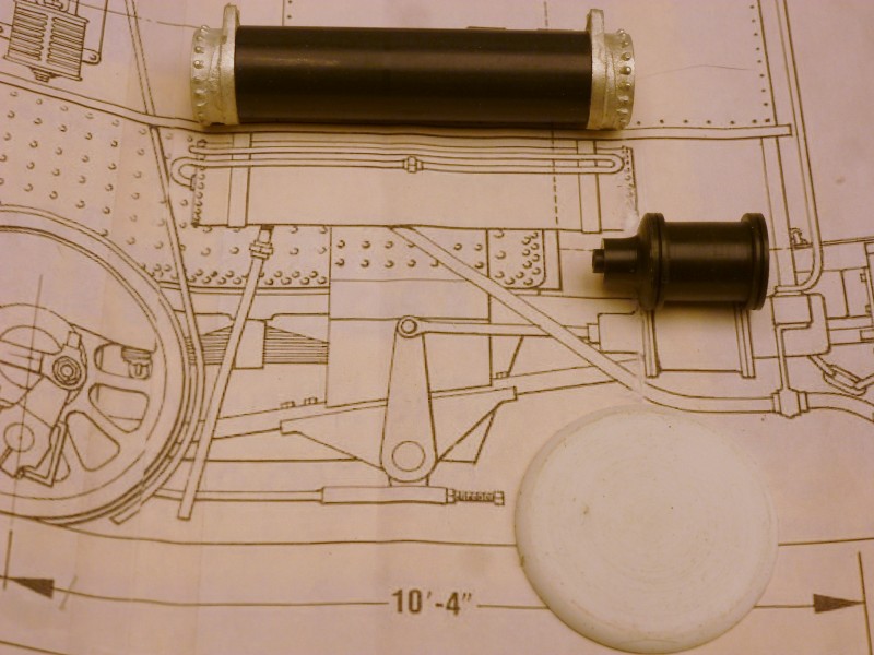
Additional
detail parts have been made. The air tank uses Ozark ends on a turned
piece of Delrin and the brake cylinder is a one piece lathe turning from
Delrin. At the bottom of the photo is a smoke box front made from the
end of a PVC pipe cap.
The
last bit of the frame has been added in the next photo. That's where
progress on the locomotive stands as of the posted update date below.
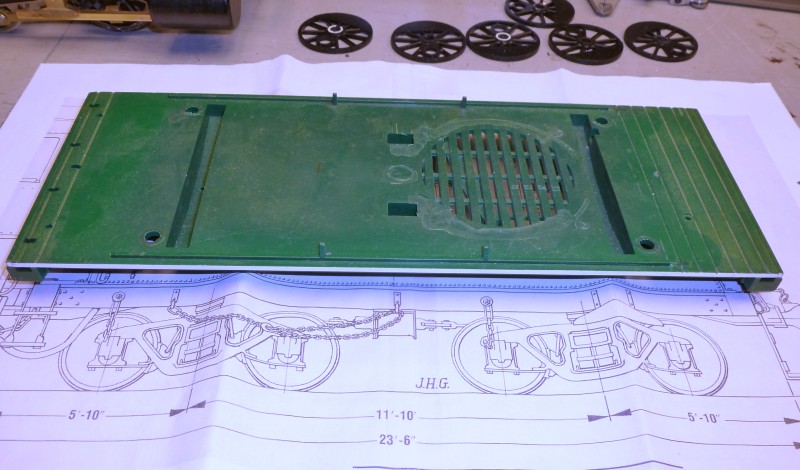
This
locomotive also needs a tender. Starting with the frame I found that a
Bachmann Annie tender frame was almost dead on for length as shown in
the next photo. It was clamped in the mill vice and all of the various
protrusions that would be in the way were milled flush with the floor.
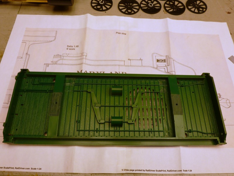
The
bolsters needed to be re-positioned so any detail that was in the area
where the bolsters needed to be was also milled away.
After
that the old bolsters were milled away, new ones salvaged from an old
car under frame were glued into the new positions.
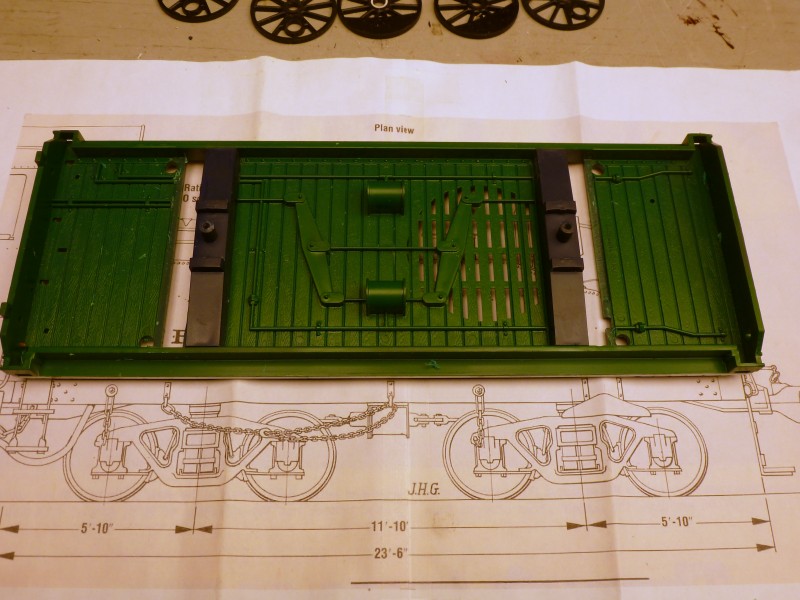
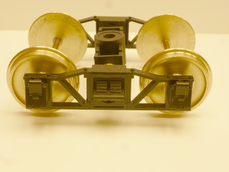
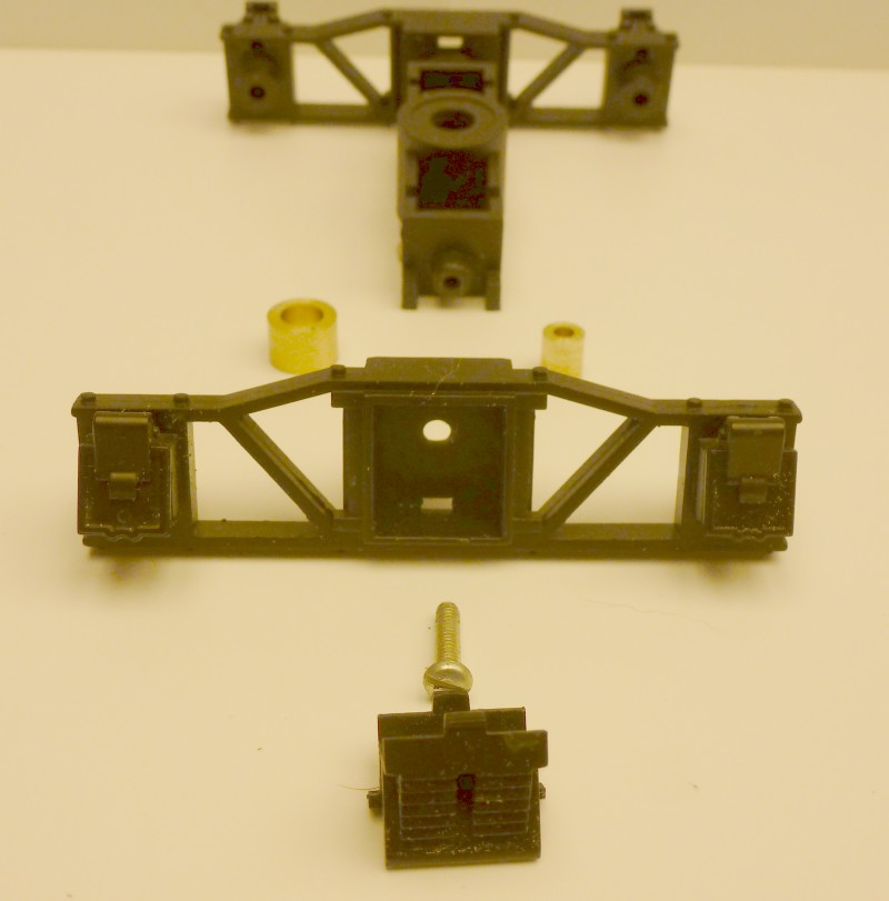
One
of the potential issues I faced was trucks. I needed a truck with a 56"
wheelbase and most of the trucks available were too short in that
dimension. Fortunately another modeler had a set of tender trucks from
one of the 1/20.3 K series locomotives that had the correct wheelbase
for 1/24 and was willing to part with them for a reasonable price. The
only thing I needed to do to them was lengthen the bolster to widen the
gauge. This was done with a couple of turned brass spacers as shown in
the photos below. I had to tap the original bolster screw hole for a
longer and non metric screw. The modification has the benefit of
providing some equalization.
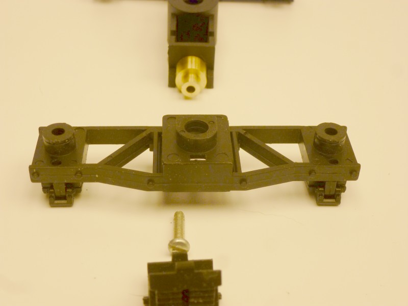
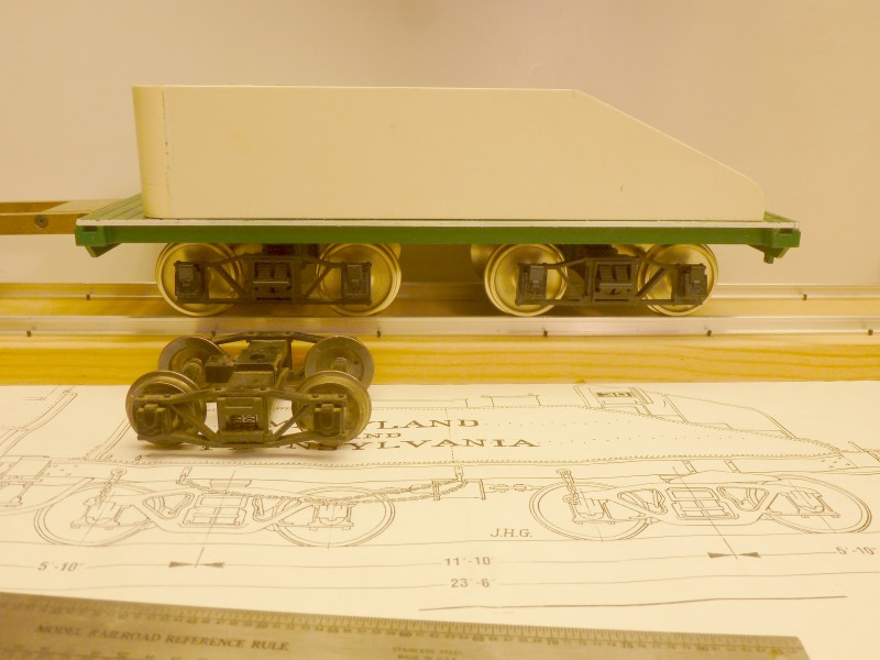
The
wheels came from Northwest Shortline. They were sized to be used as
replacement 42" wheels in 1/29 scale which works out to 33" in 1/24. I
had purchased a lot of these for use on 1/24 scale standard gauge cars.
The photo below shows the reassembled truck with the new wheels.
Unfortunately NWSL has recently announced they are closing so unless
someone buys the company and continues the line these will no longer be
available.
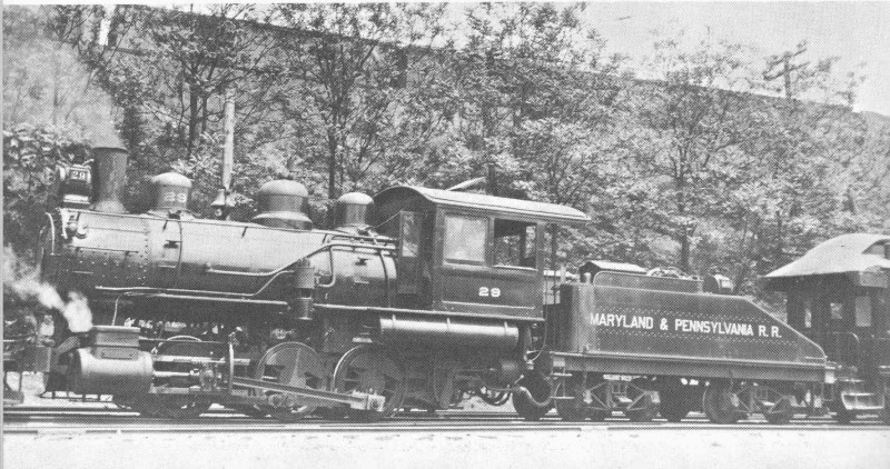
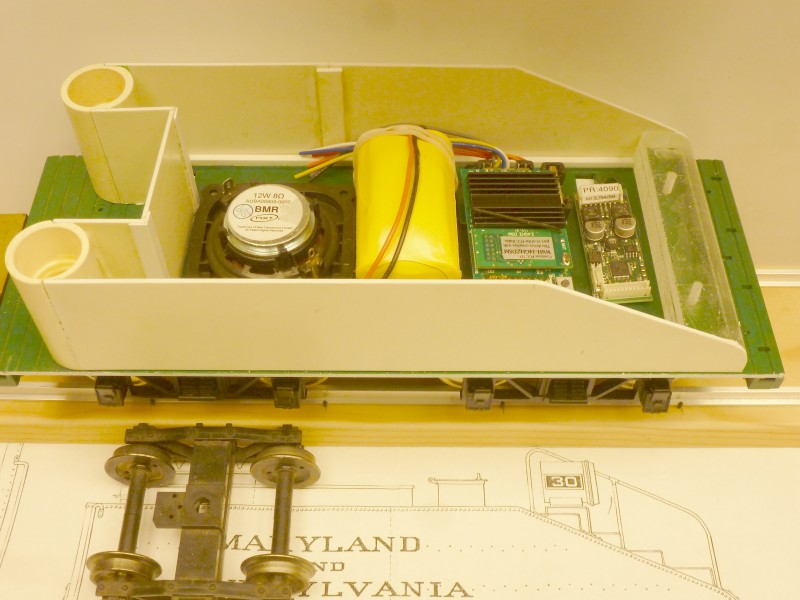
The
next photo shows them mounted under the tender with one of my standard
narrow gauge trucks for reference. While the drawing shows Bettendorf
style trucks, photos, including the one at the top of this page, show #
29 came with archbars.
The
tender shell was built up from .062" thick styrene. The front of the
water legs were made from PVC pipe. The bottom of the pipe pieces has
plug that is drilled and tapped to provide a way of securing the front
of the shell to the floor. At the back end a double thickness of acrylic
was shaped to match the back end of the side walls and was drilled and
tapped to provide a way of securing the back of the shell to the floor.
In the next photo the various items that need to be installed in the
shell have been placed to make sure they all fit. The speaker will have
a wooden box placed over it to improve sound quality . The other items
left to right are the battery pack, Revolution receiver and Phoenix
sound board.
A
piece of .020" styrene sheet was cut to fit the top and glued in place.
This is currently where the tender is in the construction process. The
next step will be to sheath it with a layer of thin styrene that has
been embossed with the hundreds of rivets as shown on the drawing. This
process is on hold while I attempt to get my semi automatic rivet
embosser working as is discussed in the article posted on the Articles
Page here.
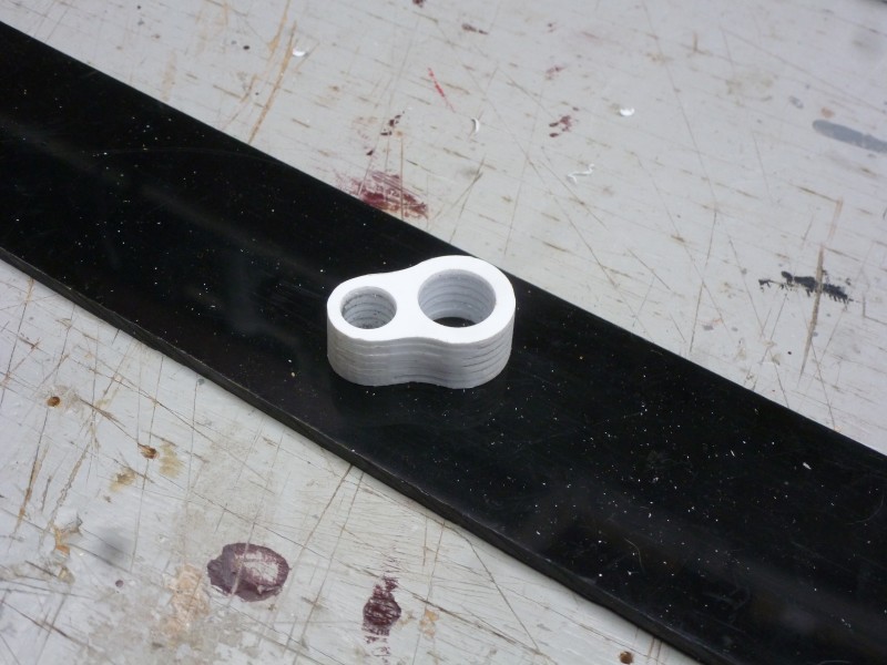
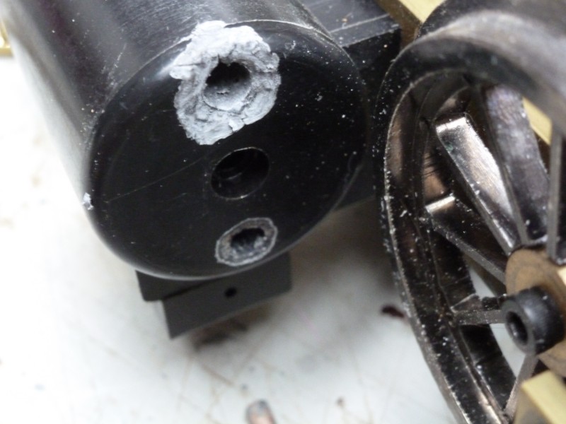
After
languishing on the shelf for the better part of a year I decided once
the outdoor season was done to get back on this project. While examining
the chassis to figure out what I needed to do next, one of the cross
head guides fell off. When I went to replace it I found what is shown in
the photo below. The delrin surrounding the mounting hole has become
crumbly, almost chalk like. This was the worst one but the other three
were showing similar signs. It appears that the silver solder flux that
I used to solder a piece of solid round stock into the end of the square
cross head guide had reacted with the delrin. While I had cleaned the
area after soldering, apparently some of the flux wicked into the
corners of the square stock and later leached out. I was surprised to
see this as delrin is impervious to most chemicals such as lacquer
thinner, acetone, MEK and alcohol. Oh well, live and learn.
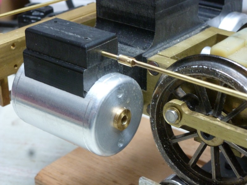
The
only delrin round stock I had on hand was some 2" which would have
required way too much time to turn and way too much wasted stock. I did
however have some 1 1/2" aluminum round stock so the 0-6-0 got a new set
of aluminum cylinders. The new cylinders added about 3 ounces of
addition weight being that much heavier than the delrin cylinders. also
as can be seen the valve actuating rod has been installed
The
most immediate goal is to finish locating all the holes that still need
to drilled in the frame so that it can be disassembled and painted.
First up was mounting the brake cylinders that I had fabricated last
year along with the actuating levers and their mounting brackets.
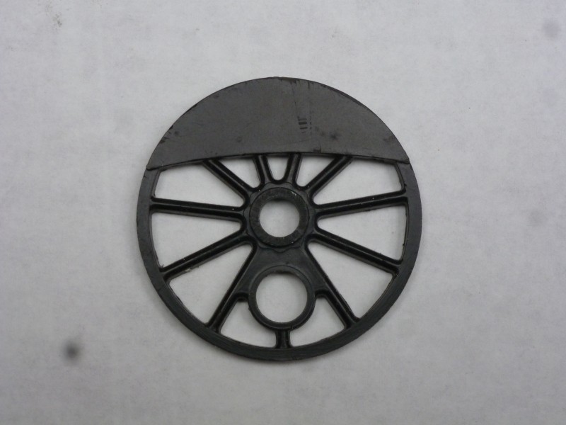
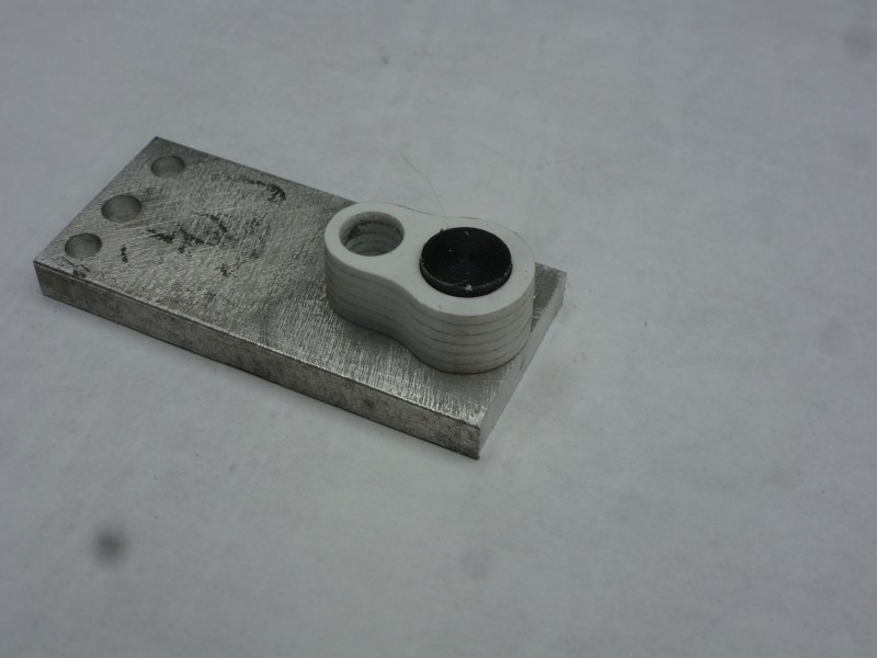
It
was also time to work on the driver center inserts. Below is the
standard Bachmann driver insert. What it needs is new centers and
counter weights to conform to the drawings.
I
didn't photograph each step here but the driver centers started out as a
stack of .060" styrene rectangles cut slightly larger than the final
pieces needed to be. These were held together for machining with pieces
of double sided tape. The stack was then place in the vice on the mill
and the two holes drilled out, starting small and working up to the
final size.
The ends were then rounded using a fixture
like the one below. The plate was set on the table of the belt and
advanced into the belt until the metal touched then it was clamped and the
stack rotated back and forth a little at a time to prevent melting until
the end was rounded. Both ends were done the same way
The
counter weights were made by cutting a circle of .060" styrene. I could
get two weights from one circle and all other cutting and shaping was
done by hand. In order to determine where the mounting points for the
boiler were to be I needed to add the firebox to the boiler. This again
was made from .060" styrene which was set into grooves milled into the
boiler and glued. The entire boiler will be covered with a thin veneer
of styrene at a later time to facilitate adding rivets. The following
two photos show progress to date. The boiler will be removed once
mounting holes have been located and drilled so that more work on it can
be done. I still need to mount brake hangers and fabricate and install
the leaf spring assemblies before the frame can be painted.