A Semi-Automatic Rivet Embossing Machine.
Most railroad locomotives and
rolling stock as well are festooned with rivets. When scratch building
these can duplicated in a variety of ways. Probably the easiest is just
to emboss them onto a piece of thin styrene and overlay it onto the
surface that needs rivets. Other options include gluing small diameter
slices of styrene rod on the surface, placing small drops of glue on the
surface or drilling holes and inserting pins or track nails. All of
those are pretty labor intensive and while OK for applications where
only a limited number are needed or they are located in areas that would
be difficult to do using the embossing method. There are also water
slide decals that come with glue dots applied to them that can be
applied in strips and some modelers have had success using them but you
do have the issue of the decal film which is best used over a glossy
surface and it can be difficult to totally hide the clear decal film.
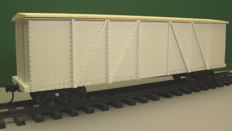
An
example of using pin heads for rivets can be seen in the photo below.
Because the rivets needed to be placed in a narrow area along a piece of
'Z' shaped styrene it was not possible to emboss them. Due to the number
required adding the rivet detail consumed most of the time required to
build this car.
When
I started my standard gauge 0-6-0 project I knew one of the issues was
going to be rivets. The number required on the locomotive was not all
that excessive but the tender was another issue all together. The
drawing showed row after row of closely spaced rivets. The thought of
drilling and installing that many pins put me off big time and caused me
to go in search of other possibilities. One of the first things that
came to mind was a sewing machine. Here was device that had a part that
moved up and down and a mechanism for moving material in incremental
steps. The feed amount was variable to provide the required number of
stitches per inch. I had an old machine that had originally been my
wife's mother's and was passed down to her and then set aside when she
got a newer model.

I
started experimenting using a cut down and properly blunted needle.
Initially results were moderately encouraging. Obviously there would
need to be some sort of guide to keep the material going in a straight
line and to set the position for a line of rivets. The first issue I ran
into was that the styrene tended to slip resulting in unevenly spaced
rivets. The advance mechanism was designed to move cloth not slippery
plastic. Increasing the pressure on the hold down foot did not help
much. I also tried laminating some card board to the back of the styrene
or using different types of tape which helped some. Another issue was
that the area below the needle was a hole to allow the needle to drop
below the surface and pick up the thread on the bobbin. This meant there
was not much in the way of back up when embossing and resulted in a less
that distinct rivet shape. I ended up spending way too much time with
this and came to the conclusion that to make it all work would require
some serious modifications to the sewing machine with no guarantee it
would work to my satisfaction in the end. A new plan was needed.
It
was then I decided to go back to my roots and try something from my
past. One of the first companies that I worked for after I mustered out
of the Air Force built systems for scanning materials being checked
using ultrasound. The accuracy for the positioning wasn't as critical as
that used in CNC machines and all that was required was a simple stepper
motor drive. The technology back in those days (early 70's) was all
discrete components and logic circuits as micro processors were in their
early stages and quite expensive. Stepper motors are still being used,
generally not in high accuracy machinery but in less demanding
applications and are commonly found in hobbyist level 3D printers, laser
cutters, hobby craft cutters like the Silhouette and other things. The
difference today versus the way we did it back then was now everything
is modular and computer controlled. The stepper motor drivers are
designed to receive inputs from computers. That was a bit of a stumbling
point for what I had in mind. Software is available that can be run on a
laptop to provide the necessary step increment to the stepper motor but
one needs to spend time learning the program and I didn't want to tie up
my laptop. Likewise one no doubt could use something like a Raspberry Pi
or Arduino with the proper programming and accomplish the same thing but
again there is that learning curve and at my age it was something I
didn't want to invest the time in just for one project.
Fortunately
some of the logic circuits from back in the day are still available and
I decided I would return to my roots and build my own pulse sequencer
using discrete components. Note: all of this at this point is only to
build an indexer to move the material to be embossed in precise and
consistent increments. I also realize this will be of limited interest
to most modelers but I'm putting it out here anyway.
First
lets look at the hardware involved. The first piece of the puzzle is a
linear slide shown in the photo below.
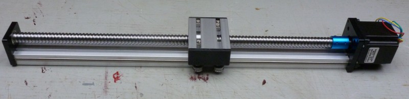
This
is a precision device. It consists of an aluminum extrusion with a steel
rod inserted in each side which protrudes far enough to engage the
rollers on the movable portion. The screw which runs from a bearing
plate at the left end to the ball bearing stepper motor at the other end
is similar to a acme type thread and is referred to as a ball screw. The
groove in the screw is sized to ball bearings which are enclosed in a
spiral track inside the ball nut which is attached to the underneath
side of the movable carriage. This ball nut is preloaded which means
that when it is screwed on ball screw the ball bearings are pressed
tightly into the grooves providing a very precision fit with very little
if any backlash. The screw has five threads per inch, this will figure
into the math later on. I've already mentioned the word stepper motor a
couple of times and for those not familiar with them you can find a
better definition here
than I can offer and includes an animated figure to illustrate how it
works as well. The stepper motor I'm using makes a 1.8º of rotation each
time the coils are are pulsed and therefore it requires 200 pulses to
make one rotation. (1.8º x 200 = 360º)
Now
for the math part. 200 pulses will rotate the ball screw 1 turn and with
5 threads per inch the screw will move the slide 1/5 of an inch or
.200". Therefore each pulse sent to the motor will index the slide
.001". Now all that is required is a circuit that will send the correct
number of pulses to move the slide the amount you want between rivets in
thousands of an inch when triggered. Is any of this making sense ? I
hope so, it's not rocket science.
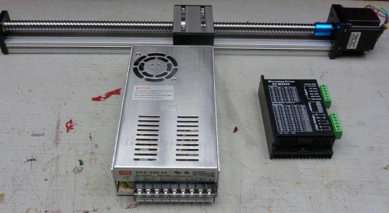
Two
other pieces of the puzzle are shown in the next photo.
The
item on the left is a regulated 24V DC switching power supply. This will
supply the power required by the motor and it's driver. It will also be
regulated down to provide power to the logic circuits needed to generate
the pulses. The device on the right is the modular motor control. It
takes the pulses from the logic circuit and drives the coils in the
motor to provide the stepping function. The unit is universal and
designed to drive a variety of different size and step angle motors, the
charts printed on the side show the positions for programming switches
on the connector side of the module. The module also accepts commands to
determine the direction of rotation, provides inputs for jogging the
motor to the initial starting position and provides stop functions that
can stop the motor when a limit has been reached.
To
date these three pieces have been tested. A square wave generator was
bread boarded to provide a constant stream of pulses to the driver
module which allowed me to run the slide back and forth and everything
so far is working as advertised. The next chore will be to bread board
the logic circuit which will read a set of thumb wheel switches. These
will be set for the index required in thousands of an inch and supply
that number of pulses to the motor driver when triggered to do so.
The
next update will be published when I have finished bread boarding and
tested the logic circuit and at that time I will go into how this will
be tied into the parts that will do the actual embossing.
Updated
3/10/19