Signals
What's that you say, signals on
a small narrow gauge line ? Well, while to my knowledge no automated
signalling was ever done on any American narrow gauge railroads, it
certainly could have. Low labor costs back in the day would have made it
less expensive to use manned posts to control trains than to invest in a
signalling system but it's my railroad and I decided I wanted some
minimal signalling. I have always been fascinated by semaphore signals
and when I saw Indiana Signal Systems semaphore signals I was hooked.
The
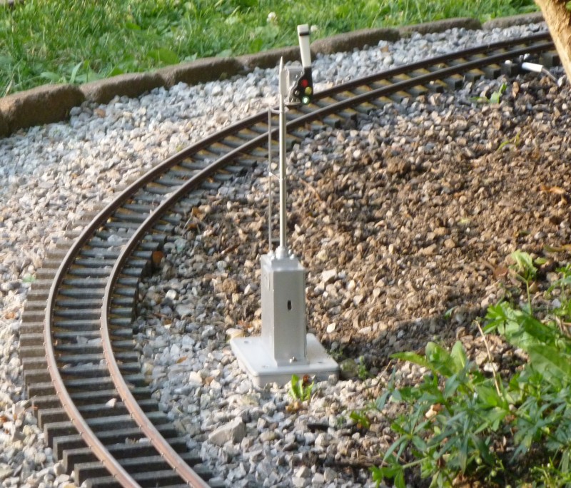
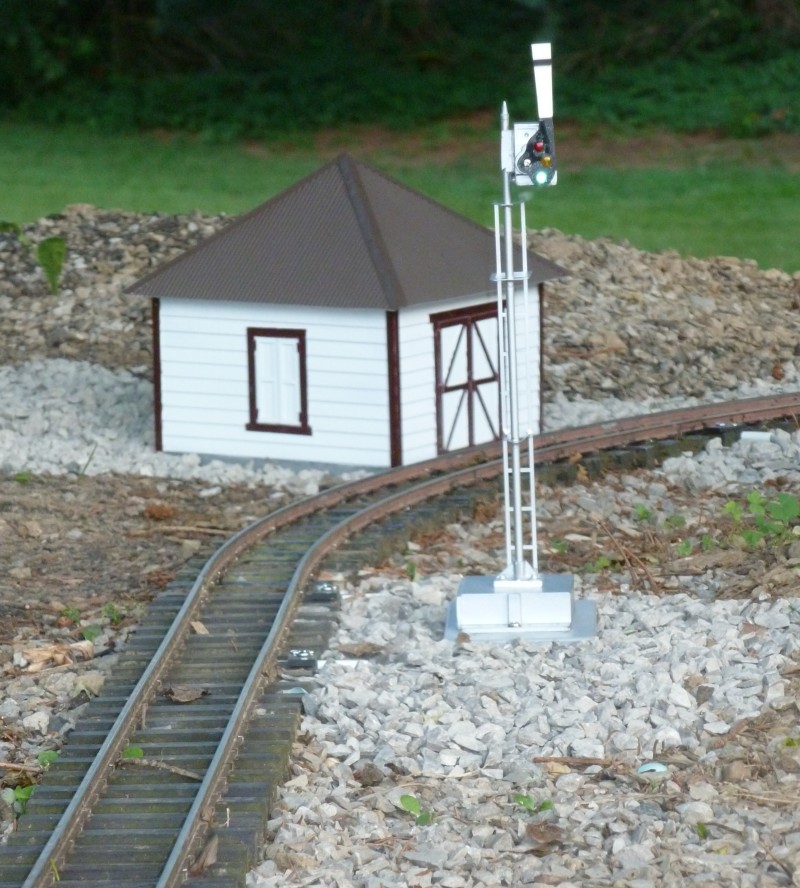
first application I had was for a signal to be located at the departure
end of the yard to let the train crews know when they were clear to
leave the yard and enter the mainline. This would be mostly for
appearance but when and if operations are staged it would provide a
method of spacing out locals as they leave the yard. The signal would
remain in the green position until such time as a train left the yard.
On it's way out it would trigger the signal to change to a red
indication and hold for some period of time before transitioning back to
green. The first semaphore I bought was set up to use photo sensors to
detect the passing train and change position and hold for an amount of
time determined by some DIP switches mounted in the control box portion
of the signal. I was dubious about how well this would work based
on my experience with these types of sensors used on industrial
machinery. Even in an indoor application various reflections and
lighting conditions can cause problems and I felt it would be even worse
outside with the effects of the sun. Turns out I was correct in my
assumptions as I had little luck getting the signal to work with any
degree of reliability. After conversing with the manufacturer it was
determined that the signal had an issue and was returned for repair.
When I got it back it did work better but I still wasn't happy with it
and after further conversation with manufacturer I was provided with the
information needed to modify the circuit so I could trigger the signal
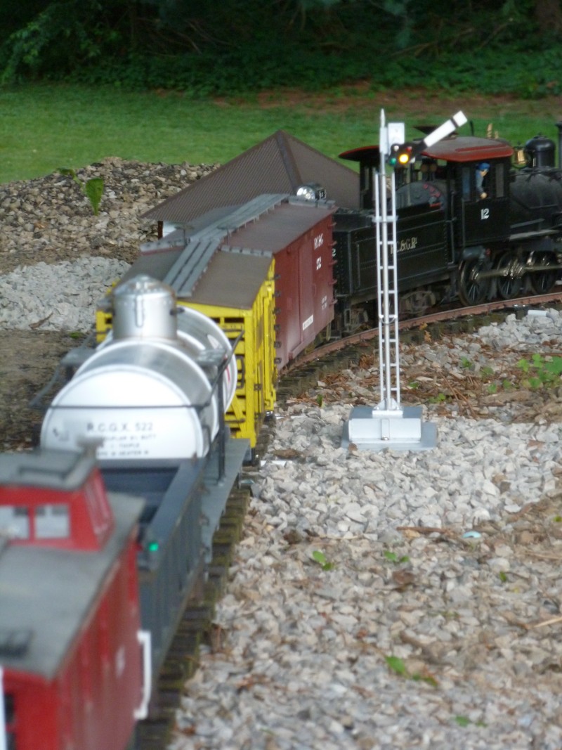
using a track side switch. Locomotives would have magnets installed to
activate a reed switch located between the ties and trigger the
signal. This was implemented and worked quite well and the magnets
would be needed for other functions later on.
The
signals themselves are not weather proof so they could not be left out
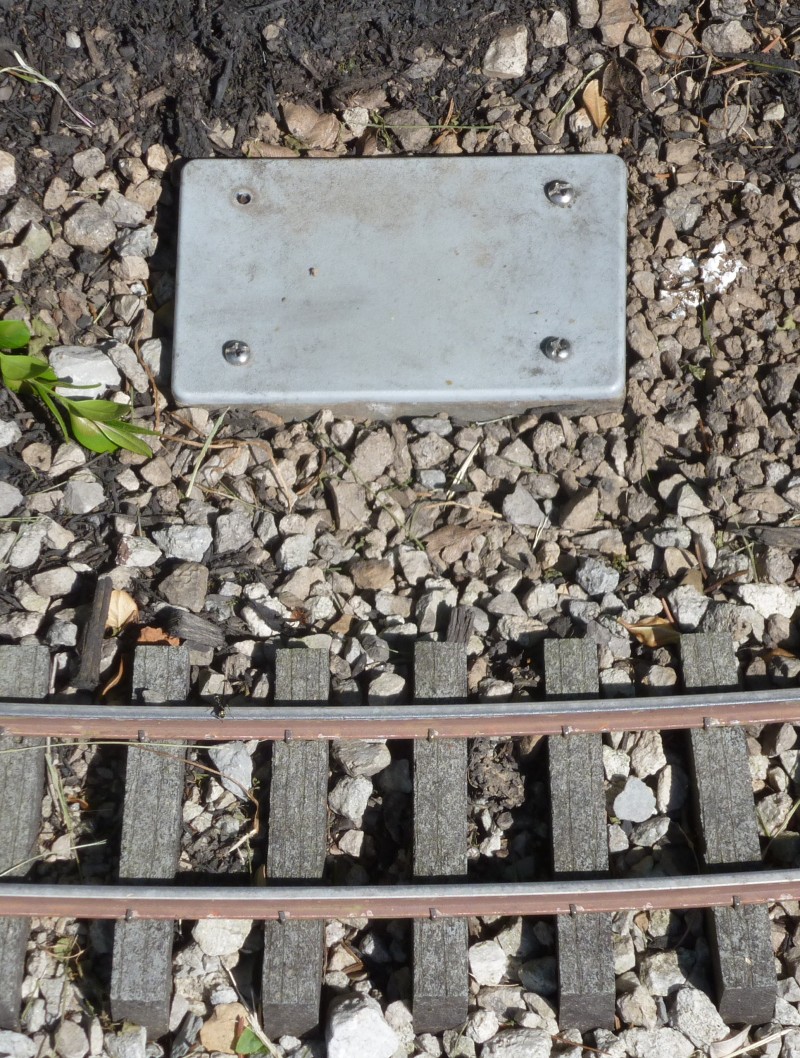
all the time. A method would be needed to allow them to put away when
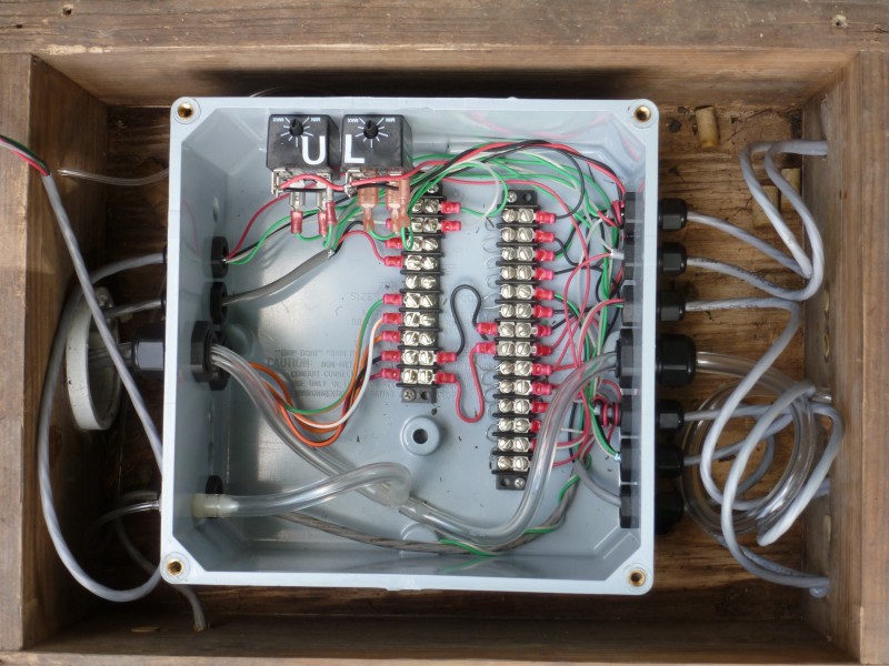
not in use. I ended up using weather proof plastic electrical boxes to
protect the electrical wiring and connectors and mounted the signals to
the lid of the box. When not being used the screws holding the lid on
are removed and a blank lid is installed in its place. The box is sunk
into the ground up to the lid. The multi conductor cable which brings
power in and connects to the under track switch enters through holes
drilled in the side of the box which are sized for a snug fit and sealed
with silicon caulk.
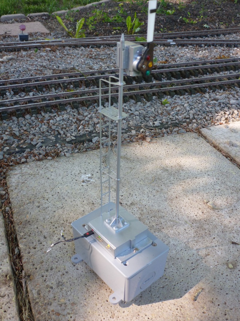
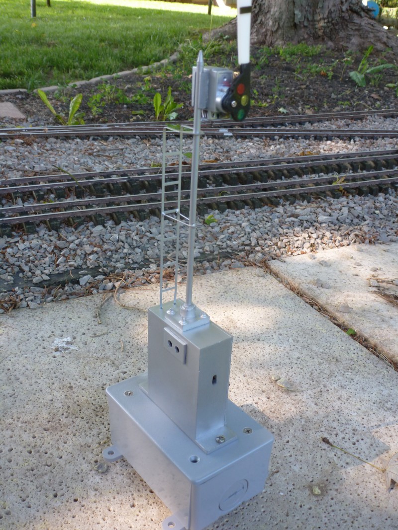
The
photo below shows the first signal purchased mounted to an electrical
box. The two holes in the side of the control base were for the photo
sensors and the one on the front was for access to the on-off switch. As
it came from the manufacturer it could be powered by a battery or
external power.