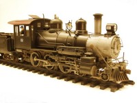
RC&G # 12
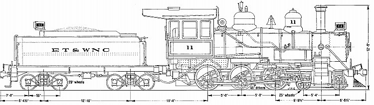
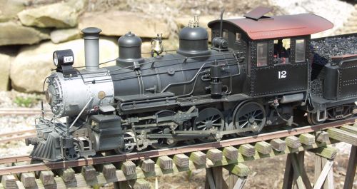
Locomotive # 12 is a Bachmann 10th anniversary special. As such it is a reasonably good facsimile of the ET&WNC's 4-6-0 # 12. It goes a long way towards fixing many of the dimensional and detailing errors that have existed since this model was introduced over ten years ago. So much so that I abandoned a long-term project that I had started to take care of a lot of the same errors. However, there were still a few areas that I felt needed addressed if one wanted make as close to the original ET&WCN prototype as possible. The drawing below shows the ET&WNC's # 11 which is virtually identical to # 12.
Since I wanted to follow the original prototype, these are the areas I addressed;
· Smokestack…I wanted
the original fluted stack as it adds a lot of class to the engine, in my
opinion.
· Wheelbase of the
pilot truck…a quick glance and comparison of the drawing to the
model reveals that on the model, the pilot truck wheels are too far
apart.
· The pilot…on
the model, it was made longer to accommodate the oversized pilot truck.
· Foot boards
between the pilot and the cylinders…prominent on the prototype but
missing on the model.
· Moving the reverse
lever to the engineer's side of the cab and adding the connecting rod
from it to the valve gear.
· Moving the valve
gear out of reverse.
· Adding a deck
plate to the cab.
· Close coupling the
tender and a few other minor changes to detailing on both the engine
and tender.
Ok, that said, this is how I went about it.
Smokestack… This is probably the easiest change to make. The skinny one supplied with the painted unlettered version just didn't look right to me so I simply swapped it with one from an older Big Hauler. Just pull it out and insert the new one.
Wheel base of the pilot
truck. This problem has been around since the beginning of Big
Hauler history and it has bugged me from day one. It was no doubt done,
along with undersized cylinders, to allow the engine to operate on
2-foot radius curves. If you are still doing this, then this change is
not for you! Bachmann corrected the cylinder size problem with the 10th
anniversary version but not the wheelbase of the pilot. The center spine
of the pilot truck was cut on both sides of the central pivot point and
about 1/4" of the spine was removed on each side. This was then spliced
back together again using a piece of aluminum bar stock that fit in the
hollow part of the spine. Holes were drilled and everything was put back
together with screws. I had found from running the engine on my line
prior to starting this project that the front truck had ample movement
in the up direction but not the down direction. This caused the truck to
derail in places where the grade transitioned down as the wheels would
be lifted from the rails. I fixed this on mine by cutting off the
plastic pin that serves and a pivot and suspension in conjunction with a
spring. I replaced the plastic piece with an aluminum standoff, of the
type used in the electronics industry. The standoff was about 1/4"
longer than the original plastic piece, which gives the truck more down
travel. The down side to this was that I had to cut away some of the
plastic material directly above the slot this mechanism travels in
provide more clearance for the longer pin. When put back together and
tested this solved my derailment problems. The aluminum also added a bit
of weight to the truck which helps it track better.
Note: this change
will affect the minimum radius on which the locomotive will operate.
It will take a 4' radius curve but nothing smaller.
The pilot… With the pilot truck modified the next logical step is to shorten pilot, which now looks way too long as a result of the pilot truck change. Unfortunately if the pilot were shortened to match the dimension on the drawing from the center of the cylinders to the end of the pilot, it results in the pilot being too close to the smoke box front. This is due to all of the parts of the pilot, the pilot beam, cowcatcher, etc. all are slightly oversized so if we just chop out a piece of the frame between the pilot beam it puts it too close to the smoke box front. As a compromise, I removed a section that moves the pilot beam to a location that looks about right when compared to the plans even if it is not exactly the right dimension.
After shortening, I spliced everything back together using a couple pieces of aluminum and screws. The pilot can take quite a bit of abuse on a locomotive this size and I felt it would be better to error on the durability side. Shortening the pilot also requires shortening the two braces between the smokebox and the pilot. Careful measurement was required to insure everything stayed straight and plumb.
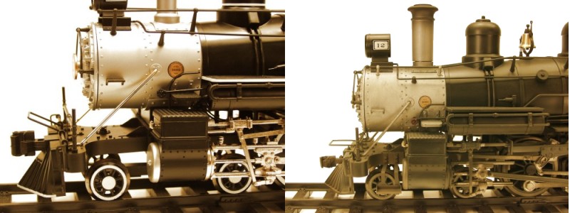
Foot boards between the pilot and the cylinders. These don't show up all that well in the drawings but are readily apparent when looking at photo's of the prototype. Again I believe they were left off the model for track radius considerations. The support brackets were fabricated from brass and are attached to the frame with 0-80 hex head screws. The steps themselves were fabricated from styrene and glued to the support brackets with Goop. As can be seen in the photos they extend out a bit further than on the prototype in order to allow the locomotive to operate on 4' radius curves.
The photo below shows the pilot area before and after the above changes.
Moving the reverse lever. Not sure why it ended up on the fireman's side on the model, it must be a Chinese thing! This is as easy as popping it loose from the cab floor and relocating it to the engineer's side. The mounting holes are already there. I did remove it from the fireman's side but did not re-install it on the engineer's side. It really doesn't show up and it made installing an engineer even tougher than it is already.
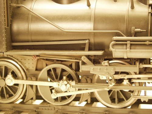
Adding the connecting rod and moving the valve gear out of reverse. The reverse lever is connected on the prototype by a rather obvious bar that runs from a slot in the cab front above the running board to a lever that connects it to the movable link in the valve gear. This is easily modeled using a strip of styrene. At the same time I decided deal with the valve gear situation. The valve gear as it comes from the factory has the moveable link set in the position that on the prototype would be reverse. Since we normally operate our locomotives in the forward direction the vast majority of the time it seemed to me that setting the valve gear to the forward would look more normal. This required quite a bit of work and if I hadn't already dismantled the loco it probably wouldn't have done it. The actuating lever runs through the center on the loco and is fixed by a block in the center through which the shaft passes. It took a bit of force but I was able to turn it some which lowered the links out of the reverse position to near neutral. To gain more travel and drop the links into the forward position required actually lengthening the link that connects the actuating lever to the adjustable link. These were made from a small piece of brass bar and screwed together. Once installed it can't be seen but does the job of putting the valve gear in the proper position for forward motion of the loco. At this time I also fabricated the missing lever that connects the reverse lever linkage from the cab to the actuating lever on the valve gear and installed in on the shaft. The completed result can be seen in the photo below.
Some detail changes.
Another thing that didn't change on the 10th anniversary addition is the
pop valve situation. Yes it has been upgraded to a metal part but there
is still only one. The FRA would not have been amused! I removed the
Bachmann part and filled the hole with a piece of styrene rod then
drilled two holes and used Ozark pop valves which were then painted a
brass color.
I also popped off the roof hatch and using a couple pieces of thin brass strips reattached it in the open position.
Adding a deck plate to the cab and close coupling the tender. I determined how close I could couple the tender by setting the locomotive and tender on a piece of 4' radius curve and made some measurements. I then made a draw bar with a pin on it that would fit the coupling hole where the hook was originally mounted on the locomotive. The draw bar was attached to the tender with a screw to a wood block I had glued to the tender floor. The dimensions for the deck plate were derived in a similar fashion with the tender coupled to the locomotive. Two pieces of small diameter brass tubing were glued to the lip along the back edge of the cab and another piece was glued to the bottom of the deck plate. A piece of piano wire that fit the inside diameter of the tubing was used to form a hinge and hold the deck plate to the back of the cab. This also allows it to move up and down with the tender as it tracks.
Miscellaneous changes. I replaced the Bachmann trucks on my tender with Aristo classics archbar trucks. I like the sprung appearance and the fact that they are equalized. I run battery power so I have more weight in the tender than I would if I were running track power. Also the Aristo trucks have a slightly longer wheelbase which more closely matches the prototype. I also put a load of real coal in the tender. I replaced the coupler in the pilot with a Kadee unit to match what I use on my other rolling stock. This is for looks only and is not functional.
There are certainly other things that could be done but I think these changes provided a visual difference that makes the locomotive stand out in a crowd and certain make it closer in appearance to its ET&WCN prototype.
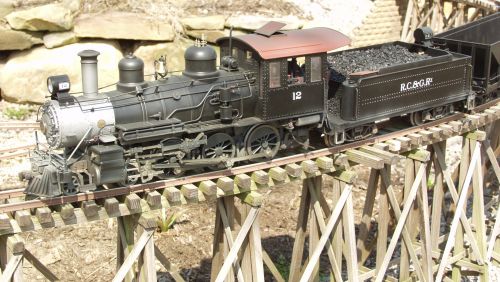
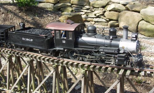
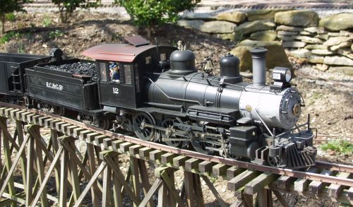
After getting a standard
RC&G paint job and lettering, a crew and a few tools and weathering
the last couple photos show the final product out on the line. On the
RC&G she will be the primary passenger lokie so the crew keeps her a
bit cleaner than the normal road engines. The finished engine at work on
the line is shown below.
Last updated 2/28/19