Automatic Control of Loop Switches
While the RC&G is designed
to provide plenty of opportunities for operations I wanted it to be
capable of running continuously for guests or times when I just want to
kick back with an adult beverage and watch it run. To that end the
layout functions as a loop to loop design and for it to be used in a
continuous running mode some method of operating the loop switches at
each end automatically.
Some
folks just use spring operated switches by my experiments with them were
less than satisfactory and I also wanted to be able to manually operate
them when doing operations so I decided to go a different route. Since
locomotives would be equipped with magnets to operate the signal system
I decided to use them to control the loop switches as well.
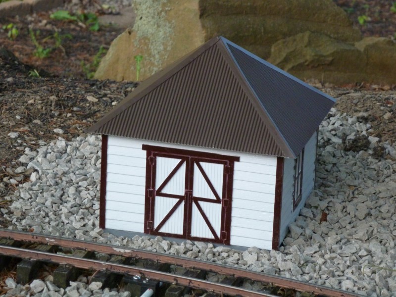
The
loop switches are operated by air cylinders and when not activated they
hold the switch points in the position for normal flow. In what I call
the automatic mode, when the locomotive completes the circuit of the
loop and is approaching the switch, its magnet will activate a reed
switch mounted under the rails. This in turn will activate a time delay
relay which applies power to an air solenoid valve which supplies air to
the air cylinder and throws the switch to the position needed. This uses
the same time delay relay as used in the signal system which is
described in another article. The relay holds the switch in the new
position long enough for the train to pass then returns to the default
position. The time is adjustable and is nominally set to 90 seconds
which is more than adequate for the train lengths and speed I use.
That's
all well and good for the automatic mode but I also needed other options
for use during operations. The two I selected are a manual mode which is
controlled by an electrical toggle switch located near the loop switch
and a radio control mode. The Revolution system I use to radio control
my locomotives also as accessory boards which can be controlled by the
hand held transmitter. By using one of these boards to activate the air
solenoid radio control can be achieved.
OK,
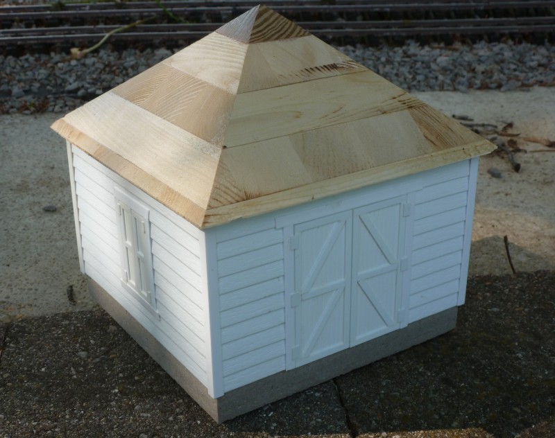
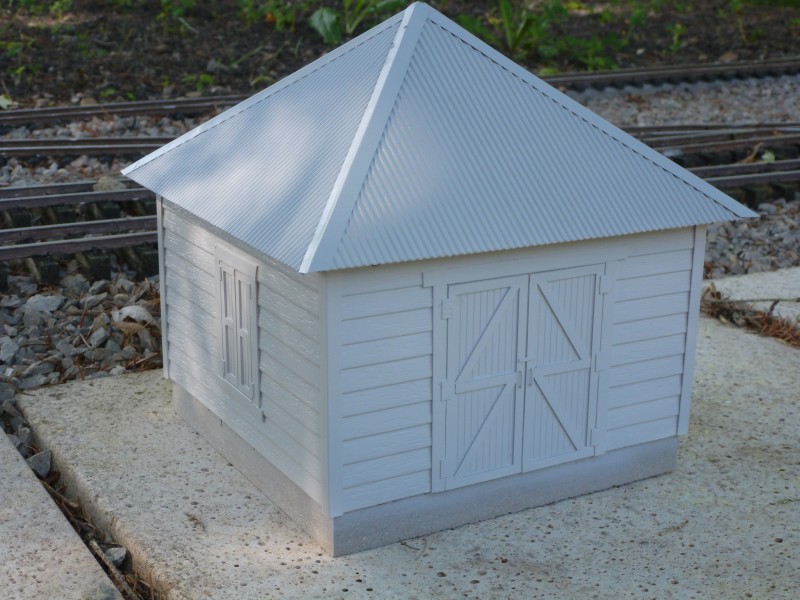
I had a plan but I needed somewhere close to the loop switches to
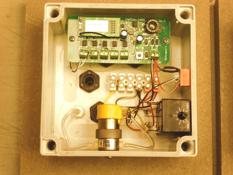
install this stuff that would be weather proof. I decided to put the
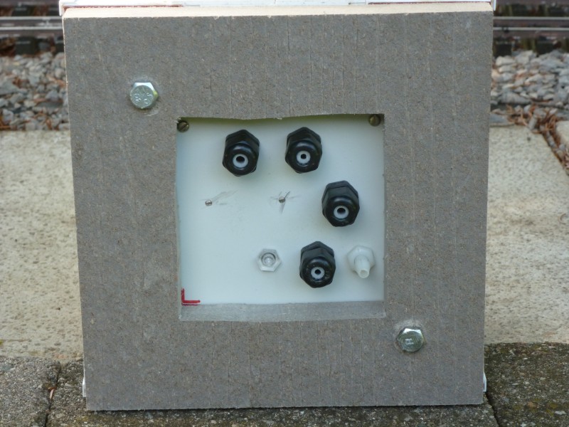
circuitry in a weather proof plastic electrical junction box. The next
photo shows the parts installed and wired up. The Revolution accessory
board is at the top, the air solenoid valve bottom center, the time
delay relay bottom right. The orange device mounted right center is a
small DC relay. This is activated by the accessory board and in turn
activates the solenoid valve. I wasn't certain that the accessory board
could handle the current required by the solenoid valve so this was
added as a safety feature. One other task this box would handle is that
of a junction box for the 12V circuit that is routed around the layout
for lighting and other devices like this. The terminal strip not only
provides tie points for the internal parts but will terminate the 12V DC
in and out lines.